Galaxy DX 98VHP Gebruikershandleiding - Pagina 3
Blader online of download pdf Gebruikershandleiding voor {categorie_naam} Galaxy DX 98VHP. Galaxy DX 98VHP 11 pagina's. 10 meter amateur mobile transceiver with built-in frequency counter & starlite face plate
IGNITION NOISE INTERFERENCE
With weak signals, you may experience interference of the signal by background
noise. This radio has NB and ANL circuits that will help reduce background noise from
sources such as your ignition system. However, background electrical noise may come
from several sources and all noise may not be eliminated. With extremely weak signals,
you can operate this radio with the engine turned off, which should improve reception.
If the ignition noise level is too high to allow proper operation under most conditions,
you should have your installation of the radio checked by a qualified technician.
ANTENNA
This radio has a jack in the rear for a standard PL-259 antenna plug. If you are
looking for the most range for your transmission, use a vertically polarized, quarter-
wave length antenna. If antenna height is a problem, you may use a shorter, loaded-type
whip antenna although you can expect some loss of transmission range.
To improve performance, your antenna should be matched to your radio. Your
antenna can be adjusted so that it matches your radio.
EXTERNAL SPEAKER
The external speaker jack (EXT SP.) on the rear panel is used for remote receiver
monitoring. The external speaker should have 8 ohms impedance and be able to handle
at least 4 watts. When the external speaker is plugged in, the internal speaker is
disconnected.
PUBLIC ADDRESS
To use the Public Address (PA) function, first connect an external speaker to the PA.
SP. Jack on the rear of the radio. See the above specifications for a proper external
speaker. Keep the speaker away from the microphone to avoid acoustic feedback.
4
CHAPTER 3 OPERATION
CONTROL FUNCTIONS
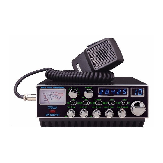
FRONT PANEL
14
15 16 17 18 19 20
B IG R IG S E R IE S
D
E
C
F
B
G
9
S
dB
A
H
PO
A M
SWR
U SB
LSB PW R
V O L
SQ
MIC
D X 9 8 V H P
O FF
1
2
3
4
5 6
1. MICROPHONE JACK: Used to connect microphone.
2. MOD LAMP: This Modulation indicator will illuminate as you speak into the
microphone. When you speak louder, it appears bright because it is on nearly 100
percent of the time and when you speak softer, it appears dimmer because it is
flickering on and off. It does not glow at all when there is no modulation. This lamp
operates in all modes.
3. MODE SWITCH: This control allows you to select one of the following operating
modes: AM/USB/LSB.
4. ON/OFF VOLUME: This knob controls the volume and power to the radio. To
turn radio on, rotate the knob clockwise. Turning the knob further will increase the
volume of the receiver.
21
22
T A L K BA C K
O FF
SW R
EC H O
+ 1 0 K H z
N B/A N L
F.D .
RB O FF
O FF
V C O FF
PA
O FF
R F
D IM
PW R
EC H O
T IME
FIN E
C O A RSE
O FF
7
8
9
10
11
12
5
23
13