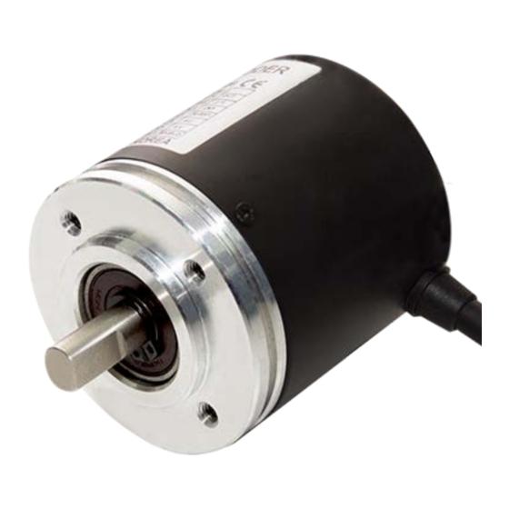
Autonics EPM50 Series Producthandleiding - Pagina 3
Blader online of download pdf Producthandleiding voor {categorie_naam} Autonics EPM50 Series. Autonics EPM50 Series 4 pagina's. 50 mm diameter absolute multi-turn rotary encoders

Specifications
Model
EPM50S8-1013-B-PN-24-□
Single-turn: 1024 division, 10 bit
Resolution
Multi-turn: 8192 revolution, 13 bit
Rotation limit when
± 90°
power OFF
01)
Output code
Binary 2 code
Output signal
Single-turn data, Multi-turn count, Overflow alarm (OVF)
Parallel NPN open collector
Control output
output
Inflow current
≤ 32 mA
Residual voltage
≤ 1 VDCᜡ
Outflow current
-
Output voltage
-
Output logic
Negative logic output
Response speed
≤ 1 ㎲
03)
Single-turn data reset
04)
Input level: 0 - 1 VDCᜡ
Multi-turn count reset
05)
Input logic: Low Active, OPEN or HIGH in common use
Direction
Input time: ≥ 100 ms
Clear
Input level: 0 - 1 VDCᜡ
Input logic: Low Active,
Latch
OPEN or HIGH in
common use
Input time: ≥ 500 μs
Clock
-
Max. response freq.
50 kHz
Max. allowable
3,000 rpm
revolution
06)
Starting torque
≤ 0.0069 N m
≤ 40 g·cm
Inertia moment
2
Allowable shaft load
Radial: 10 kgf, Thrust: 2.5 kgf
Unit weight
≈ 475 g (≈ 560 g)
(packaged)
Approval
ᜢ ᜫ
01) It calibrates the multi-turn count by comparing single-turn data before/after power off without counting multi-
turn count when power off. Correct multi-torn count cannot be obtained if a rotating operation exceeding ± 90°
is performed at the rotation position when power off.
02) Outputs when multi-turn count is out of counting range (0 to 8191 revolution).
03) Based on cable length: 2 m, I sink = 32 mA
04) If the single-turn data reset signal is applied, the single-turn data will be initialized to 0.
05) If the multi-turn count reset signal is applied, the multi-turn count will be initialized to 0.
06) For parallel model Select resolution to satisfy Max. allowable revolution ≥ Max. response revolution
max. response frequency
[max. response revolution (rpm) =
resolution
12 - 24 VDCᜡ ± 5% (ripple P-P: ≤ 5%)
Power supply
Parallel NPN open collector output: ≤ 100 mA (no load)
Current consumption
SSI Line driver output: ≤ 150 mA (no load)
Insulation resistance
Between all terminals and case: ≥ 100 MΩ (500 VDCᜡ megger)
Dielectric strength
Between all terminals and case: 750 VACᜠ 50 / 60 Hz for 1 minute
1 mm double amplitude at frequency 10 to 55 Hz (for 1 minute) in
Vibration
each X, Y, Z direction for 2 hours
Shock
≲ 50 G
Ambient temp.
-10 to 70 ℃, storage: -25 to 85 ℃ (no freezing or condensation)
Ambient humi.
35 to 85%RH, storage: 35 to 90%RH (no freezing or condensation)
Protection rating
Axial cable type: IP64 (IEC standard), Radial cable type: IP50 (IEC standard)
Connection
Axial / Radial cable type model (cable gland)
Ø 6 mm, 2 m, shield cable
Cable spec.
Parallel NPN open collector output: 17-wire × 2,
SSI Line driver output: 10-wire
AWG28 (0.08 mm), insulator diameter: Ø 0.8 mm
Wire spec.
Parallel NPN open collector output: 17-core,
SSI Line driver output: 19-core
EPM50S8-1013-B-S-24-□
24 bit, Binary 2 code
SSI (Synchronous Serial Interface)
Line driver output
≤ 20 mA
≤ 0.5 VDCᜡ
≤ -20 mA
≥ 2.5 VDCᜡ
-
-
-
Input level: 5 VDCᜡ ± 5%
Input frequency: 100 kHz to 1
MHz
-
(4 × 10
kg·m
)
-6
2
≈ 324 g (≈ 409 g)
× 60 sec
]
Output Waveform
• Following waveform is based on the positive logic.
(In case of negative logic, the waveform is opposite to corresponding waveform.)
■ Parallel open collector output type single-turn data (1024 division)
0
1
2
3
4
2
0
02)
TS
2
1
2
2
2
3
.
.
.
2
8
2
9
■ Parallel open collector output type multi-turn count (8192 revolution)
0
1
2
3
4
2
0
TS
2
1
2
2
2
3
.
.
.
2
8
2
9
2
10
2
11
2
12
■ SSI Line driver output timing chart
t1
T=1/f
CLOCK
n
n-1
DATA
MSB
t2
■ SSI Line driver output type data output
OVF
M12
OVF
Clock input
Data
bit
output
1
OVF error
2
3
4
5
6
7
Multi-turn
8
count
9
10
11
12
13
14
5
6
7
8
9
1020
1021
1022
1023
0'
.
.
.
5
6
7
8
9
1020
1021
1022
1023
.
.
.
Clock Frequency f 100 kHz to 1 MHz
t3
T
1
0
Time lag t2
LSB
Monoflop Time t3 15 ㎲ < t3 < 30 ㎲
···
M1
M0
S9
S8
Multi-turn count
Data output
Clock input
bit
bit
0 bit
15
12 bit (MSB)
16
11 bit
17
10 bit
18
9 bit
19
8 bit
20
7 bit
21
6 bit
22
5 bit
23
4 bit
24
3 bit
2 bit
1 bit
0 bit (LSB)
8188
8189
8190
8191
0'
.
.
.
T: 1 to 10 ㎲
0.5 ㎲ < t1 < 5 ㎲
t2 < 0.3 ㎲
···
S1 S0
Single-turn data
Data
Data output
output
bit
9 bit (MSB)
8 bit
7 bit
6 bit
5 bit
Single-turn
data
4 bit
3 bit
2 bit
1 bit
0 bit (LSB)
