Autonics ARD-DO16NE Handmatig - Pagina 3
Blader online of download pdf Handmatig voor {categorie_naam} Autonics ARD-DO16NE. Autonics ARD-DO16NE 8 pagina's. Devicenet digital remote i/o
Ook voor Autonics ARD-DO16NE: Handmatig (8 pagina's)

DeviceNet Communication
Item
Specifications
I/O Slave messaging (Group 2 Only slave)
Communication
·Poll command: Yes ·Bit_strobe command: Yes ·Cyclic command: Yes ·COS command: Yes
Communication distance
Max. 500m (125kbps), Max. 250m (250kbps), Max. 100m (500kbps)
NODE ADDRESS setting
Max. 64 nodes (set by the front rotary switch)
Communication speed
125, 250, 500kbps (automatically set when connecting with Master)
I/O and inner circuit: Photocoupler isolated, DeviceNet and inner circuit: non-insulation,
Insulation
DeviceNet power: non-isolated
DeviceNet power
·Rated voltage: 24VDC ·Voltage range: 12-28VDC ·Power consumption: Max. 3W
Approval
ODVA Conformance tested
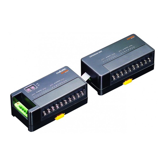
Unit Description
Basic unit
● Standard terminal block type
2
3
4
1
7
● Sensor connector type
2
9
8
Expansion unit
● Standard terminal block type
2
1
5
● Sensor connector type
4
1
2
DeviceNet Digital Remote I/O
1. DeviceNet connector
5
No.
5
4
6
3
2
1
2. Rotary switch for node address
: Rotary switch for setting node address.
×10 represents tens digit and ×1 represents ones digit.
3
3. Status LED: It displays the status of unit (MS) and network (NS).
4. I/O status LED: It displays each I/O status.
5. Rail lock: It is used for mounting DIN rail or with screw.
6. Connector output part: It connects an expansion unit.
6
7. I/O terminal block: It is used for connecting external device I/O.
5
8. Sensor connector: It is used for connecting external device I/O.
4
9. External power connector: It is used for supplying external power.
1
3
4
1. Connector input part
: It connects expansion unit and is joined into
expansion connector output.
2. I/O status LED: It displays each I/O status.
3. Rail lock: It is used for mounting DIN rail or with screw.
3
4. Connector output part: It connects an expansion unit.
5. I/O terminal block: It is used for connecting external device I/O.
7
6. Sensor connector: It is used for connecting external device I/O.
7. External power connector: It is used for supplying external power
6
Color For
Organization
Red
24VDC (+)
White CAN_H
None Shield
Blue
CAN_L
Black 24VDC (-)
V+
CAN_H
SHIELD
CAN_L
V-
(A)
Photoelectric
Sensors
(B)
Fiber
Optic
Sensors
(C)
Door/Area
Sensors
(D)
Proximity
Sensors
(E)
Pressure
Sensors
(F)
Rotary
Encoders
(G)
Connectors/
Sockets
(H)
Temperature
Controllers
(I)
SSRs / Power
Controllers
(J)
Counters
(K)
Timers
(L)
Panel
Meters
(M)
Tacho /
Speed / Pulse
Meters
(N)
Display
Units
(O)
Sensor
Controllers
(P)
Switching
Mode Power
Supplies
(Q)
Stepper Motors
& Drivers
& Controllers
(R)
Graphic/
Logic
Panels
(S)
Field
Network
Devices
(T)
Software
S-7
