Galletti UGR S Handmatig - Pagina 3
Blader online of download pdf Handmatig voor {categorie_naam} Galletti UGR S. Galletti UGR S 4 pagina's. Remote control panel
PCD
PCD
PCD
PCD
PCD
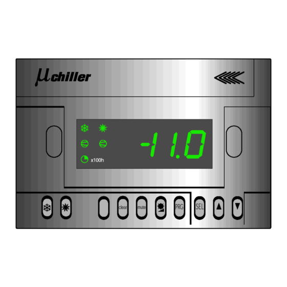
DESCRIPTION OF PCD REMOTE CONTROL PANEL
GB
The PCD remote control panel allows you to rapidly set the machine operating
parameters, display them at any time and obtain an immediate picture of the machine
operating status.
The display contains 3 digits and 5 LEDs for indicating the operating mode, displaying
the parameters set or measured and signalling any alarms that have been triggered.
The PCD remote control terminal is supplied in two different versions, depending on
the chilling unit it will be combined with:
CHILLING UNITS
UGR S, UGRS E, UGR/HS Mod. Code. 1701545
6÷44, MCA, MCA H
ECHO ECHO H
UGR S, UGRS E, UGR/HS Mod.
52÷80
Code. 1701530
UGRV E Mod. 80÷100
INSTALLATION OF PCD FOR UGR S, UGRS E, UGR/H S MODELS 6÷44, MCA, MCA
H, ECHO, ECHO H (COD. 1701545) AS SHOWN IN FIGURE 1
- Install the serial converter (figure 1b) in the guide track situated near the
terminal block of the electric control board (figure 1a);
- Using the wire provided, connect the serial converter to the electronic
regulator already installed on the electric control board of the unit;
- Then connect wires 0V and 24V, situated on the control board, respectively
with serial converter terminals 11 and 12 (figure 1a);
- Connect the serial converter and remote terminal following the directions shown
on the machine wiring diagram or using the numbers of the terminals of the two
components as your reference; use a shielded cable with three twisted pairs
(maximum length 150 m) to make this connection and connect the cable shield to
earth.
- After making all the electrical connections, check the position of the four
microswitches on the electronic card inside the remote terminal; microswitches
1 and 2 should be in the OFF position, while numbers 3 and 4 should be ON.
When the power supply to the machine is turned on, the letters "CN" will appear on
the display (error in communication with remote terminal) since the regulator is still
set for only one terminal. To enable the second terminal you must change the parameter
H8 either from the remote terminal or using the electronic controls on the machine;
carry out the following steps:
1) Keep the "SEL" and "PRG" keys pressed down together for at least 5 seconds
until the flashing digits 00 appear on the display (figure 2);
2) Using the "UP" and "DOWN" keys set the number on the display to 177, which
is the password for changing parameters. Then press the "SEL" key to confirm
the selection and access the programming mode;
Note: once the procedure has been activated, if no key is pressed during the next
60 seconds the control will go back to the normal operating mode without storing
any parameters that may have been changed.
3) Once you have accessed the programming mode, you can view the codes of all
the parameters by pressing the "UP" and "DOWN" keys;
4) Run through the parameters until you reach H8 (the parameter that establishes
the number of terminals) and press "SEL" to display the setting;
5) Change the default setting from 0 to 1 to enable the second terminal. Then press
"PRG" to memorise the new setting.
WARNING
: do not change the settings of the other parameters; any changes
may cause the unit and its safety devices to cease working efficiently.
Remote contacts
The electronic regulator is equipped with remotely controlled contacts that allow you
to turn the unit on and off or switch between summer and winter.
These contacts can be disabled so that the ON/OFF and summer-winter changeover
functions may be activated solely from the electronic controls and remote terminal.
Conversely, enabling the contacts will partly limit the possibility of activating the ON/
OFF and summer-winter changeover functions with the electronic controls and remote
terminal, as is explained below.
The remote contacts can be enabled and disabled by changing some parameters of
the electronic regulator. The steps to follow are the same as those described previously
for changing the parameter H8.
Enabling the remote ON/OFF contact:
If H7 = 1 (default setting) the remote ON / OFF contact will be enabled; if the contacts
of the remote ON/OFF are open the machine will remain off and disabled; if they are
closed, the machine will be enabled and may be turned on or off using either the
electronic regulator on the machine itself or the remote terminal.
Disabling the remote ON/OFF contact:
If the parameter H7 is instead set on 0, the remote ON / OFF contact will be disabled;
in this case the machine can be turned on or off as desired using either the electronic
regulator on the machine itself or the remote terminal.
Enabling the remote "summer-winter changeover" contact:
For chilling units with heat pumps, you can enable or disable the remote summer/
winter contact by changing the parameter P8.
If P8 = 3 (default setting) the summer-winter contact is enabled: the machine will work
only as a chilling unit if the summer-winter contact is open; conversely, if the summer-
winter contact is closed, the machine will work only as a heat pump.
Therefore in this case (P8=3) the operating mode can only be changed by means of
the summer-winter contact; the summer-winter changeover function of the electronic
regulator on the machine and the remote terminal will be disabled.
PCD
DOTAZIONE
remote terminal
serial converter
connecting wire
remote terminal
remote control card
connecting wire
Disabling the remote "summer-winter changeover" contact:
If P8 = 0 the summer-winter contact is disabled; the machine can be switched to
the desired operating mode using either the electronic regulator on the machine or
the remote terminal.
INSTALLATION OF PCD FOR UGR S, UGRS E, UGR/H S MODELS 52÷80 AND
UGRV E MODELS 80/1÷100/1 (CODE 1701530) AS SHOWN IN FIGURE 3
- Install the remote control card on the four spacers provided near the main
card of the electric control board (see layout of electric control board);
- Disconnect the wire attached to the electronic regulator from the main card;
- Using the wire provided with the remote control card, connect the main card to
the remote control card;
- Connect the wire attached to the electronic regulator (previously disconnected
from the main card) to the remote control card;
- Connect the remote control card and the remote terminal, using the numbers of
the terminals of the two components as your reference; use a shielded cable
with three twisted pairs (maximum length 150 m) to make this connection and
connect the cable shield to earth.
- After making all the electrical connections, check the position of the four
microswitches on the electronic card inside the remote terminal; microswitches
2 and 3 should be in the OFF position, while numbers 1 and 4 should be ON.
When the power supply to the machine is turned on, the letters "CN" will appear on
the display (error in communication with remote terminal) since the regulator is still
set for only one terminal. To enable the second terminal you must change the H8
parameter either from the remote terminal or using the electronic controls on the
machine; carry out the following steps:
1) Keep the "SEL" and "PRG" keys pressed down together for at least 5 seconds
until the flashing digits 00 appear on the display (figure 2);
2) Using the "UP" and "DOWN" keys set the number on the display to 177, which
is the password for changing parameters. Then press the "SEL" key to confirm
the selection and access the programming mode;
Note: once the procedure has been activated, if no key is pressed during the
next 60 seconds the control will go back to the normal operating mode without
storing any parameters that may have been changed.
3) Once you have accessed the programming mode, you can view the codes of all
the parameters by pressing the "UP" and "DOWN" keys;
4) Run through the parameters until you reach H8 (the parameter that establishes
the number of terminals) and press "SEL" to display the setting;
5) Change the default setting from 0 to 1 to enable the second terminal. Then
press "PRG" to memorise the new setting.
Warning: do not change the settings of the other parameters; any changes
may cause the unit and its safety devices to cease working efficiently.
Remote contacts
The electronic regulator is equipped with remotely controlled contacts that allow
you to turn the unit on and off or switch between summer and winter.
These contacts can be disabled so that the ON/OFF and summer-winter
changeover functions may be activated solely from the electronic controls and
remote terminal.
Conversely, enabling the contacts will partly limit the possibility of activating the
ON/OFF and summer-winter changeover functions with the electronic controls and
remote terminal, as is explained below.
The remote contacts can be enabled and disabled by changing some parameters
of the electronic regulator. The steps to follow are the same as those described in
the previous section.
Enabling the remote ON/OFF contact:
If H7 = 1 (default setting) the remote ON / OFF contact will be enabled; if the
contacts of the remote ON/OFF are open the machine will remain off; if they are
closed, the machine will remain on.
Disabling the remote ON/OFF contact:
If the parameter H7 is instead set on 0, the ON / OFF remote contact will be
disabled; in this case the machine can be turned on or off as desired using either
the electronic regulator on the machine itself or the remote terminal.
Enabling the remote "summer-winter changeover" contact:
For chilling units with heat pumps, you can enable or disable the remote summer-
winter contact by changing the parameter H6.
If H6 = 1 (default setting) the summer-winter contact is enabled: the machine will
work only as a chilling unit if the summer-winter contact is open; conversely, if the
summer-winter contact is closed, the machine will work only as a heat pump.
Therefore in this case (H6=1) the operating mode can only be changed by means
of the summer-winter contact; the summer-winter changeover function of the
electronic regulator on the machine and the remote terminal will be disabled.
Disabling the remote "summer-winter changeover" contact:
If H6 = 0 the summer-winter contact is disabled; the machine can be switched to
the desired operating mode using either the electronic regulator on the machine or
the remote terminal.
3
GB
RG66000496 - rev. 02