Galls Street Thunder ST280 Handleiding voor installatie en gebruik - Pagina 7
Blader online of download pdf Handleiding voor installatie en gebruik voor {categorie_naam} Galls Street Thunder ST280. Galls Street Thunder ST280 20 pagina's. Siren amplifier & light controller
Ook voor Galls Street Thunder ST280: Handleiding voor installatie en gebruik (18 pagina's)
(Electrical Connections CONT'D)
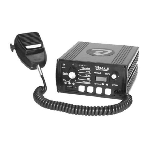
Siren input and output
connections are made on
the back of the unit through
a 12-pin connector and
wiring harness.
WIRING GUIDE
Description
Color
Terminal
1
Power
2
Ground
Black
3
Radio Repeat
4
Power
5
Ground
Black
6
Radio Repeat
7
Speaker
Brown
8
Park Kill
9
Backlighting
Orange
10
AUX Out
Green
Ignition
Switched
11
Yellow
Power
12
Speaker
Brown
Mandatory Electrical Connections For Siren Functions
BLACK:
(Pins 2 & 5) Ground - Connect these leads to the negative of the
battery, or to a good chassis ground.
leads if you are using two 100-watt speakers. Be sure to use minimum
size #14 AWG wire.
RED:
(Pins 1 & 4) Power - Connect both leads to the positive side of the battery, or
to a high current power buss.
using two 100-watt speakers. A power relay may also be used. Be sure to
use minimum size #14 AWG wire.
YELLOW:
(Pin 11) Ignition Switched Power - Connect to +12VDC through a
switched power supply (possibly ignition). This will turn the siren on and
off. Be sure to use minimum size #18 AWG wire.
Note: The siren WILL NOT function unless +12VDC is present on this wire.
ORANGE:
(Pin 9) Backlight Power - This lead supplies power for the backlighting of
the siren. Connect it to +12VDC from the dash lights, parking lights or
other switched source. Be sure to use minimum size #18 AWG wire.
BROWN:
(Pins 7 & 12) Speaker Output - Connect one lead to each terminal or
lead of the speaker. Be sure to use minimum size #14 AWG wire. If
connecting a second speaker in parallel, you must observe the polarity
of the speakers (phasing). Be sure that the positive terminals of both
speakers are connected together to the same brown wire from the
siren. In which case, the negative terminals of both speakers would
also be connected together to the other brown wire.
3
2
1
6 5
4
9
8
7
1 2
1 1
1 0
Typical
Current
Red
10A
10A
Blue
0.1A
Red
10A
10A
Blue
0.1A
4A
RECOMMENDED WIRE GAUGE
Gray
0.1A
Current
0.1A
< 2.0A
3A
2.0-4.0A
0.1A
4.1-5.5A
5.6-8.0A
4A
8.1-12.0A
You MUST connect both leads if you are
-5-
10'
20'
25'
22 AWG
18 AWG
18 AWG
18 AWG
16 AWG
16 AWG
18 AWG
16 AWG
14 AWG
16 AWG
14 AWG
14 AWG
16 AWG
12 AWG
12 AWG
You MUST connect both