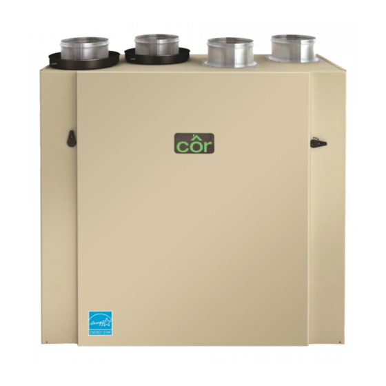
Cor HRVCRSVU1157 Handleiding voor installatie-instructies - Pagina 9
Blader online of download pdf Handleiding voor installatie-instructies voor {categorie_naam} Cor HRVCRSVU1157. Cor HRVCRSVU1157 17 pagina's. Heat recovery ventilator

INSTALLING TWO EXTERIOR HOODS
Choose an appropriate location to install the exterior hoods:
S There must be a minimum distance of 6- ft (1.8 m) between the
hoods to avoid cross- contamination
S There must be a minimum distance of 18- in (457 mm) from the
ground
Make sure the intake hood is at least 6 feet (1.8 m) away from the
following:
S Dryer exhaust, high efficiency furnace vent, central vacuum vent
S Gas meter exhaust, gas barbecue grill
S Any exhaust from a combustion source
S Garbage bin and any other sources of contamination
Refer to figure beside for connecting insulated ducts to the exterior
hoods. An "Anti- gust intake hood'' should be installed in regions
where a lot of snow is expected to fall.
Exhaust hood
Intake hood
18-in
(457 mm)
6-ft
(1.8 m)
Fig. 17 - Exterior hoods
Connecting the drain
Cut 2 sections of the plastic tube, at least 16- in (406 mm) long,
and attach them to each inner drain fitting, located under the unit.
Join both short sections to the "T" junction and main tube as
shown in Fig. 18.
16"
(406 mm)
Fig. 18 - Drain connection
6-ft
(1.8 m)
Optional
duct location
18-in
(457 mm)
Tape and duct tie
A11206
16"
(406 mm)
A11208
Make a water trap loop in the tube to prevent the unit from drawing
unpleasant odors from the drain source. Make sure this loop is
located OVER the "T" as shown. Run the tube to the floor drain or
to an alternative drain pipe or pail.
IMPORTANT: If using a pail to collect water, locate the tube end
approximately 1- in (25 mm) from the top of the pail in order to
prevent water from being drawn back up into the unit.
± 1"
Fig. 19 - Drain connection
CONTROLS
This unit is equipped with an integrated control located under the
unit, on the recessed side of electrical compartment. Plug the unit.
Unit booting sequence
The unit booting sequence is similar to a personal computer boot
sequence. Each time the unit is plugged in after being unplugged,
or after a power failure, the unit will perform a 30- second booting
sequence before starting to operate.
During the booting sequence, the integrated control LED will light
GREEN (unit set in normal defrost) or AMBER (unit set in
extended defrost) for 5 seconds, and then will shut off for 2
seconds. After that, the LED will light RED for the rest of the
booting sequence. During this RED light phase, the unit is
checking and resetting the motorized damper position. Once the
motorized damper position completely set, the RED light turns off
and the booting sequence is done.
NOTE: No command will be taken until the unit is fully booted.
Integrated control
Use the push button (1) to control the unit. The LED (2) will then
show on which mode the unit is in. See Fig. 20.
2
1
Bottom of the unit
Fig. 20 - Integrated control
9
A11209
A11210
