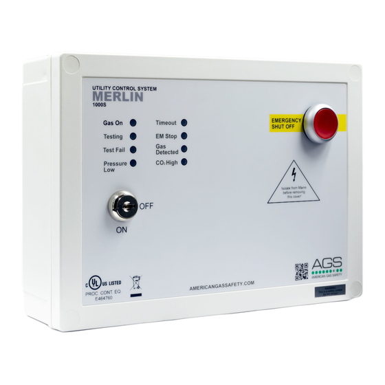
AGS Merlin 1000S Installatie- en bedieningshandleiding - Pagina 6
Blader online of download pdf Installatie- en bedieningshandleiding voor {categorie_naam} AGS Merlin 1000S. AGS Merlin 1000S 12 pagina's. Gas utility isolation controller
Ook voor AGS Merlin 1000S: Gebruikers- en installatiehandleiding (10 pagina's), Installatie-, Bedienings- en Onderhoudshandleiding (10 pagina's), Installatie- en bedieningshandleiding (16 pagina's)

Installation & Operation Manual
4. PRESSURE SENSOR
The pressure sensor is wired to the [PRESSURE SENSOR] connector and screwed into the downstream
port of the gas solenoid valve. Connect the pressure sensor as shown:
Wiring: Red
[+]
Black [-] Blue
The sensor will monitor the gas supply pressure and if pressure drops below 0.17psi –
the gas valve will close as this could mean a gas leak is present.
The pressure sensor operating pressure is: 0 – 1.45psi.
5. EM REMOTE
Connections for remote emergency shut-off or stop buttons is detailed on the circuit board as [EM
REMOTE]. This is linked out as a factory setting. Remote emergency shut-off buttons should be volt free
and wired to the Merlin 1000S using a plenum security cable, white, 18/2 (18AWG 2 conductor),
stranded, CMP or similar.
6. GAS DETECTOR
Connections can be made for a Merlin gas detector (LPG, NG,
CO or Hydrogen).
If no detector is being used leave the factory fitted link in.
A wiring example is shown.
Refer to your gas detector manual for further information.
7. FAN SWITCHES
This terminal switches when the key is turned on and off.
This can be connected to a fan switch (supplied separately) which can provide power to fans when the
control panel is switched on.
8. CO2 MONITOR
This terminal can be used to connect a Merlin CO
concentration of CO
.
2
If no CO2 monitor is connected, the panel will 'beep' upon power up and the CO2 LED will flash 3 times
to indicate that this terminal has been disabled. An external power supply is required.
Refer to your CO
monitor manual for further information.
2
9. 12V DC
This is a power output for external auxiliary devices when there is power at the panel and can be used to
create a relay switch with the BMS relay output.
Max output: 50mA
Rev: 10
02-21
[
]
IN
monitor to shut off the system in the event of a high
2
Merlin 1000S
6
