Dea Ghost 100/EN Bedieningsinstructies en waarschuwingen - Pagina 4
Blader online of download pdf Bedieningsinstructies en waarschuwingen voor {categorie_naam} Dea Ghost 100/EN. Dea Ghost 100/EN 17 pagina's. Underground electro-mechanical operator for swing gates

2 PRODUCT DESCRIPTION
Models and contents of the package
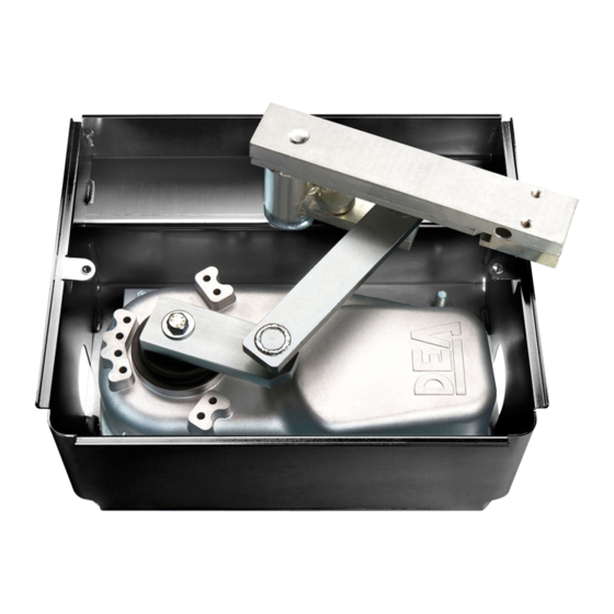
The name GHOST 100 identifies a series of underground electro-mechanical operators for the automation of swing gates with diffe-
rent features depending on motor phase power supply and the presence of the encoder.
GHOST 100 is completed by a set of accessories listed in the "PRODUCT ACCESSORIES" table (page 38).
GHOST 100 is an electromechanical operator for swing gates rotating an articulated arm. This arm is connected to the gate to be
operated by means of the lever unit of the foundation box. The lever unit, that will be properly welded at the time of installation, has a
built-in operator unlocking device which will allow you to open the gate even if there is a power supply failure.
Inspect the "Contents of the Package" (Pic. 1) and compare it with your product for useful consultation during assembly.
Transport
GHOST 100 is always delivered packed in boxes that provide adequate protection to the product, however, pay attention to all infor-
mation that may be provided on the same box for storage and handling.
3 TECHNICAL DATA
Motor power supply voltage (V)
Absorbed power (W)
Max torque (Nm)
Duty cycle (cycles/hour)
Maximum n° of operations in 24 hour *
Built-in capacitor (µF)
Operating temperature range (°C)
Motor thermal protection (°C)
Opening time 90° (s) *
Maximum opening degree
Weight of product with package (kg)
Protection degree
* The data refer to the use in combination with NET series control boards and with parameters of speed and slowdown set as per default.
4 INSTALLATION AND ASSEMBLY
4.1
For a satisfactory installation of the product is important to:
• Verify that the structure complies with the regulations and then define the complete design of the installation;
• Make sure the gate is well balanced and there aren't points of friction while closing and opening;
• Identify an area that allows a smooth and safe manual operation of the operator;
• Ensure that the foundation box dimensions are conformable with the selected area for the assembly (Pic. 2);
• Provide a stop stroke in closing and possible also in opening;
• Use the lenght/weight diagram and installation dimensions provided (Pic. 4) for a correct positioning of the box with respect to the
door to be
moved.
4.2 Once you have defined and satisfied these requirements, proceed with the assembly:
• Dig a hole suitable for the type of ground using the dimensions shown in Pic. 3 as a reference;
• Prepare an adequate number of channels for the passage of electric cables and drainage in order to avoid water build up;
WARNING All operator wirings must be run outside of the foundation box and inside proper watertight cases. To ensure the product
protection degree, the power supply cable of the operator must not be cut.
• Position the box inside the hole making sure that the pin is alligned with the axis of the hinge (Pic. 4);
• Start setting the concrete and, before it dries, make sure it is perfectly levelled;
Wait for the concrete completely dry;
• Insert the ball on the shaft provided on the box and then the release lever assembly;
Warning: properly lubricate the pivot point;
• Place the door of the gate on the release pin and fix the two parts with a good weld;
• Place the operator inside the foundation box making sure that it is inserted in the right direction (Pic. 5);
• Secure the motor with the appropriate washers and nuts supplied;
• Connect the lever of the gearbox to the release mechanism, with the junction bracket;
6
100 - 100/CL - 100EN/CL
230 V ~ ±10% (50/60 Hz)
250
250
18
100
10
-20 ÷ 50 °C
150 °C
16
100/EN
100/24 - 100/24CL
24 V
25
110°
11
IP67
50
200
40
100
-
-
14
