Jaga JRT-200 Installatie, installatie en gebruikershandleiding - Pagina 2
Blader online of download pdf Installatie, installatie en gebruikershandleiding voor {categorie_naam} Jaga JRT-200. Jaga JRT-200 4 pagina's.
Ook voor Jaga JRT-200: Installatie, instellingen en gebruik (16 pagina's)
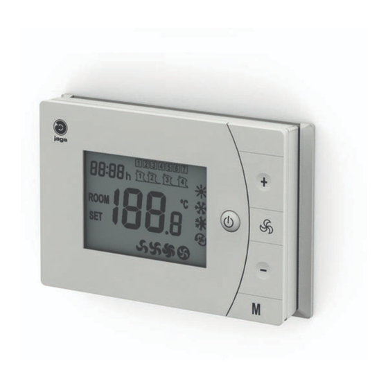
Jaga Room Thermostat JRT-200 installation
Installation
WIRING: Warning: The installation of the thermostat should be performed by qualified personnel and must comply with the applicable
local and national electrical codes and utility requirements. All wire connections must be tightened and properly arranged to prevent
a shortcircuit. Turn off the power at the electrical panel to prevent electrical shock or product damage.
To remove the wall plate, use a Phillips
screwdriver to loosen the two screws from
the bottom of the wall plate
24V AC/DC
24V AC/DC
24V AC/DC
24V AC/DC
24V AC/DC
24V AC/DC
11
10
9
8
7
6
5
4
11
10
9
8
7
6
5
4
11
10
9
8
7
6
5
4
11
10
9
8
7
6
5
4
11
10
9
8
7
6
5
4
11
10
9
8
7
6
5
4
• flush wiring can enter from the rear
through the aperture in the wall plate
• connect the JRT-200 according the wiring
diagrams** on this page
Warning: Turn off the power at the electrical panel to prevent electrical shock or product damage.
** Wiring diagram
11
10
9
8
11
7
L
L
24V / 220VAC
24V / 220VAC
N
N
H/C
Heating / Cooling
H
Heating
Remove the front panel
3
2
1
3
2
1
3
2
1
3
2
1
3
2
1
3
2
1
Reassemble the front panel
2-Pipe
-
+
10
6
9
5
8
4
7
3
6
2
5
1
4
3
+
DC 24V
-
C
Cooling
GND
N
-
+
2
1
11
10
9
8
11
7
+
DC 24V
L
L
-
24V / 220VAC
24V / 220VAC
N
N
When not using a recessed conduit box:
• mark out and drill the holes
• screw the device to the wall.
The type of wall, solid or cavity, determines
the type of screw or plug that is used.
Tighten the screws with a Phillips screwdriv-
er. (Do not over-tighten.)
4-Pipe
-
+
10
6
9
5
8
4
7
3
6
2
5
1
4
3
+
DC 24V
-
25 juni 2018, 8:45 - Jaga N.V.
M
M
M
M
M
M
-
+
2
1
+
DC 24V
-