Jäger Direkt OPUS 55 SENS Installatiehandleiding - Pagina 3
Blader online of download pdf Installatiehandleiding voor {categorie_naam} Jäger Direkt OPUS 55 SENS. Jäger Direkt OPUS 55 SENS 6 pagina's. Temperature-humidity sensor
Installation guide
OPUS 55 SENS Temperature-humidity sensor
Battery operation Art. No. 563.043.37, 563.043.43, 563.043.51, 563.043.66; incl.
power supply unit art. no. 563.044.37, 563.044.43, 563.044.51, 563.044.66
1. Product description
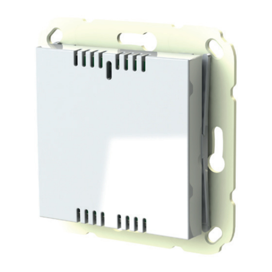
OPUS 55 SENS is an intelligent sensor for the detection of temperature and humi-
dity, suitable for single room control as well as for integration into common smart
home applications. Available in four different colors, OPUS 55 SENS comple-
ments any popular 55 switch program, especially the OPUS 55 designs.
It can be operated either with a battery or with the help of an additional power
supply unit as part of the building installation technology. Based on the integra-
ted EnOcean radio module, the purely battery-powered OPUS 55 SENS can be
installed in almost any conceivable mounting position and is therefore particularly
suitable for existing buildings.
The supplied bracket is either screwed or glued and simplifies surface mounting of
the sensor. In connection with an external power supply, OPUS 55 SENS is con-
nected to the house installation in a flush-mounted switch box (deep), which all-
ows a permanent power supply. Optional: In combination with an external sensor,
OPUS 55 SENS detects leakage situations and reports them immediately. The
sensor stores and communicates a short-term occurrence of leakage for 14 days.
1.1 Specifications
Power supply
Measuring ranges
Measuring cycle
Transmission cycle
SIGNAL Message
Leakage (optional)
Ambient conditions
EnOcean radio
Protection class
1.2 Intended use
OPUS 55 SENS is used to measure room temperature and relative humidity in-
doors. In combination with qualified accessories, it is used to detect leakage in the
environment of water installations.
OPUS 55 SENS has been developed for domestic use and similar fixed installations.
Prior to installation, check the suitability on the basis of the technical data and the
operating conditions. OPUS 55 SENS must not be used in conjunction with life-sup-
porting devices or with products that may cause danger to the life or limb of people
and animals or to property.
1.3 Warranty
The guarantee expires if Opus 55 Sens is not used according to its intended use
if not qualified accessories are connected when the housing is opened or if other
interventions are carried out on the device.
JÄGER DIREKT · OPUS Straße 1 · 64646 Heppenheim · [email protected] · www.myOPUS.eu
Battery: Type CR2450,
operating time > 7 years (typ.)
external power supply 230 V AC
Temperature: 0 °C ... +50 °C,
humidity: 0 % rh ... 100 % rh
120 seconds
2 min. at change >0.2°C or
>5 % rH, 20 min. maximum
every 240 minutes
external, 2 detection zones;
sending with state change,
14 days history
from -10°C to +50°C, max 98 % rH,
non-condensing
868,3 MHz ASK max. 10 mW
IP30
2. Installation and commissioning
2.1 Battery operation
For initial commissioning, pull out the isolation tab
on the back of the OPUS 55 SENS in the direction
of the arrow and remove it. The inserted battery is
thereby connected and the OPUS 55 SENS performs
a restart. At this point, the sensor sends a standard-
ized teach-in telegram (UTE). Subsequently, it sends
a measured value ten times in succession every 2
minutes.
The SIGNAL messages transmit both the energy status and the version of the device
for the first time within 5 minutes after commissioning. After removing the isolation
tab, place the separately available 1-fold frame on the bracket. Then insert the OPUS
55 SENS into the frame and snap it into place (see Fig. 2).
Frame
OPUS 55 SENS
BATTERY REPLACEMENT:
Press a tool, e.g. a commercially available screwdriver
or a nail (not included in the scope of delivery) into the
slot, for unlocking on the front of the OPUS 55 SENS
and pull the device out of the frame (see Fig. 3). Re-
place the battery in the battery compartment on the
back. Place the frame, insert the OPUS 55 SENS and
snap it into place.
2.2 Mains operation via ext. power supply unit
In combination with the external power supply unit, OPUS 55 SENS is simply
installed on a flush-mounted switch box (deep) with 230 V supply voltage.
The power supply unit is connected to the power supply using commer-
cially available terminals according to the connection diagram (see Fig.
4). It is important to note that the circuits are separated in accordan-
ce with the insulation regulations for protection class II. During installa-
tion, the 230 V cable must be behind the power supply unit and the con-
necting cable with 4-pin socket must be in front of the power supply unit.
Wall bracket/
Wall plate