Centurion POLOphone Installatiehandleiding - Pagina 2
Blader online of download pdf Installatiehandleiding voor {categorie_naam} Centurion POLOphone. Centurion POLOphone 17 pagina's. Entry panel
Ook voor Centurion POLOphone: Installatiehandleiding (16 pagina's), Installatiehandleiding (17 pagina's), Inbedrijfstellingsprocedure (4 pagina's)

System overview & operation
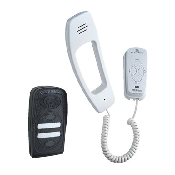
The CENTURION POLOphone is a very versatile intercom system designed for a multitude of applica-
tions ranging from a basic 1 to 1 kit to larger installations with up to five components in the system. A
component is either an entry panel or a handset as detailed below.
Expandability
The POLOphone system can be configured using combinations of up to five components as follows:
Up to two entry panels
Two groups of handsets with up to three handsets per group.
The system can operate without an entry panel connected.
Each call button rings one or both of the groups of handsets, depending on the mode set.
Intercommunication is available between the two groups of handsets.
1 to 1
Handset
Entry
Panel
Fig 1 Excellent expandability using only two wires
Wiring
The system uses a two wire bus to link all the components, making the wiring of the system particularly
easy.
Powering the system
The POLOphone system operates off a DC supply and can therefore be powered from either a 14V DC
mains adaptor or directly from the battery supply of a 12V gate motor system.
The power source can be connected to any component in the system.
Other features
Using the same two wire bus, each handset can independently operate the door lock or gate motor
linked to each entry panel. The entry panel is provided with a potential-free, normally-open contact to
operate either a gate motor or, in series with a separate power supply, to activate a door lock.
An auxiliary, potential-free, normally-open pushbutton is also provided on each handset. This
pushbutton does not connect to the two wire bus and requires separate wiring to operate an auxiliary
function on the gate motor or at the entrance such as switching an external light etc.
A fourth button is provided on each handset to call the handsets in the other handset group.
A small window is provided on the face of the handset cradle for the indicator light (LED). The terminals
for this LED are on the underside of the cradle circuit board. These can be wired to a gate motor status
function etc. Similar to the auxiliary pushbutton, additional wiring is required.
Permanent backlighting of the entry panel call button(s) and identification label(s) are provided.
Page 2 - POLOphone Intercom
4 to 1
Handsets
Intercommunication
Handsets
Intercommunication
Entry
Panel
3 to 2
Entry
Panels
