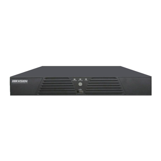
HIKVISION DS7208HVI-ST Product-/onderhoudshandleiding - Pagina 16
Blader online of download pdf Product-/onderhoudshandleiding voor {categorie_naam} HIKVISION DS7208HVI-ST. HIKVISION DS7208HVI-ST 18 pagina's. Ds-7200hvi-st series dvr
Ook voor HIKVISION DS7208HVI-ST: Technisch handboek (13 pagina's), Snelstarthandleiding (9 pagina's), Technisch handboek (9 pagina's)

- 1. Ds7208Hvi-St/Sn Equipment Physical Interface
- 2. Ds7208Hvi-St/Sn Equipment Internal Structure
- 3. Ds80061 Mainboard Hardware Principle Diagram
- 4. Ds80061 Mainboard Hardware Modules Diagram
- 5. Ds80061 Mainboard Hardware Module Introduction
- 6. Network Module
- 7. Power Supply Module
- 8. Ds80061 Mainboard Failure Analysis
⑤.RS485 Failure
Step 1: the first to exclude thermistors JK250 (RPT1/2)
Step 2: measurement TVS tube B03NC (BA2/7) impedance, or replacement
Step 3: measurement 6L184 6and 7 feet chip difference voltage (normal close
to 5 V), or replacement
⑥. Internet Links
Network light and network data transmission light are flashing
Step 1: first measurement RTL8201 chip PIN 36 input voltage 3.3V is normal, or
to measure WCX (FBN1) impedance, or replacement
Both network light and network data transmission light not bright
Step one: first measurement 25 M (Y3) crystal, or replacement
Step two: replace RTL8201
Both network light and network data transmission light are nomal
Step one: first replace RTL8201, and then ruled out MS10232, BV03C
(TVS32/17)
⑦.SATA Hard Dish Fault
Step one: first measurement BD9329 (U1) PIN 3 power output voltage wheather 5V or short
circuit, or replacement
⑧. Clock Fault
Step one: the first to rule out the battery (normal voltage 3.3 V), and then ruled
out 8563 T, 32768 HZ, diodes
⑨.VGA Output Color Devation
Step 1: measuring 75Ω resistance (RG4/5/6), or replacement
Step 2: measurement BAV99 (Q3/7/8) PIN 3 impendance to GND, or
replacement
Step 3: rule out 6303 chip
