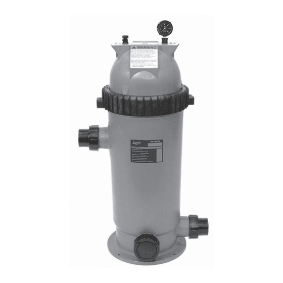
Figure 2.
Typical Piping Installation
2.
If the pump is located below water level,
isolation valves must be installed on both the
suction and return lines to prevent the back flow
of pool water during any routine or required
servicing.
WARNING
Some Safety Vacuum Release System (SVRS)
devices are not compatible with installation of check
valves. If the pool has an SVRS device, be sure to
confirm that it will continue to safely operate when
any check valves are installed.
3.
Install the pump such that any disconnecting
means and/or junction boxes for power
connection are withing sight of the pump and at
least five (5) feet horizontally from the edge of
the pool and/or spa. Choose a location that will
minimize turns in the piping.
NOTE
In Canada, the minimum distance maintained from
the edge of the pool and/or spa as noted above must
be 3 meters (10 feet), as required by the Canadian
Electrical Code (CEC, CSA C22.1).
4.
The pump should be installed on a firm, solid, and
level surface to avoid risk of settlement. Do not
use sand to level the pump as sand will wash away.
Check local building codes for any additional
requirements (Ex. Equipment pads in Florida must
be concrete and equipment must be secured to the
pad.)
NOTE
Zodiac Pool Systems LLC recommends bolting the
pump directly to the foundation.
5.
The pump foundation must have adequate drainage
to prevent the motor from getting wet. The pump
needs to be protected from the rain and sun.
6.
Proper ventilation is required for the pump
to operate normally. All motors generate heat
that must be removed by providing proper
ventilation.
Jandy
Pro Series FHPM Pump
®
|
Installation & Operation Manual
AQUAPURE
7.
Provide access for future service by leaving a
clear area around the pump. Allow plenty of
space above the pump to remove the lid and
basket for cleaning.
8.
If the equipment is under cover, provide
adequate lighting.
3.1.3
Replacement of Existing Pump
Jandy Pro Series FHP pumps can easily replace several
other pumps: the Hayward
Super II, Pentair
Jandy Pro Series
MaxHP (MHP), Sta-Rite
Glas II, Sta-Rite Dyna-Glas
Sta-Rite Max-E-Pro
To replace the Pentair WhisperFlo, Jandy Pro Series
PHP, or Jandy Pro Series MHP, use the FHP's adjustable
base. The FHP base (and its spacers) increase the total
height of the pump and the height of the suction side of
the pump. See Table 1 and Figure 3.
Table 1.
FHP Dimensions
Base Configuration
1. Pump without
Base
2. Pump with Base
3. Pump with Base
and Spacers
4. Pump with Small
+ Large Base
3.1.3.1
Install Spacers into Small Base
1.
Using a hand cutter tool, cut the plastic bars
connecting the top and bottom sets of spacers,
as shown in Figure 4.
2.
Push the two (2) top spacers and two (2) bottom
spacers out of the base.
ENGLISH
MANUAL BY-PASS DETAIL
MANUAL BY-PASS IS USED
WHEN FILTRATION RATE
EXCEEDS 125 GPM
Super Pump
®
®
SuperFlo
, Pentair
WhisperFlo
®
®
®
, PlusHP (PHP), Jandy Pro Series
®
Dura-Glas
, Sta-Rite Dura-
®
®
, Sta-Rite Max-E-Glas
®
, and Sta-Rite SuperMax
®
Suction Side
Pump Height
Height
¾
7
" (197 mm)
12
9" (229 mm)
14" (356 mm)
¼
9
" (235 mm)
14
⅞
10
(276 mm)
15
Page 7
, Hayward
,
®
,
®
.
®
¾
" (44 mm)
¼
" (362 mm)
⅞
(403 mm)

