Garmin GPSMAP 17 Installatiehandleiding - Pagina 10

Blader online of download pdf Installatiehandleiding voor {categorie_naam} Garmin GPSMAP 17. Garmin GPSMAP 17 16 pagina's. Gps receiver/antenna
Ook voor Garmin GPSMAP 17: Handleiding voor installatie-instructies (16 pagina's), Handleiding voor installatie-instructies (12 pagina's), Referentiehandleiding (1 pagina's), Technische referentie (30 pagina's), Handleiding voor installatie-instructies (17 pagina's), Handleiding voor installatie-instructies (19 pagina's), Conformiteitsverklaring (1 pagina's), Technische specificaties (40 pagina's), Snelstarthandleiding (16 pagina's)
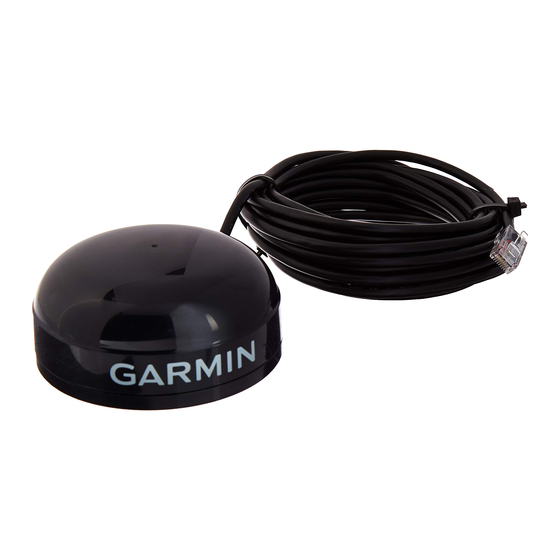
Garmin GPSMAP 17 Installatiehandleiding
W
GPS 17
IRING THE
W
IRING THE
After mounting the GPS 17 in the desired location, connect
the wiring. Connect the GPS 17's Port 1 Data In, Data Out,
Remote On/Off, and Ground (Return) lines to your NMEA
device or PC. Port 2 is used for RTCM input only.
For reliable communication, it is essential that the GPS
17 and the receiving device share the same ground. This
ground connection acts as the (signal) Return line. Wire
the unit to its own circuit to avoid interference from other
electronics.
You need a DB-9 or DB-25 serial connector (normally
female) if you are connecting the GPS 17 to a PC. Check
with a PC or electronics supplier for these items.
4
9
8
7
6
DB-9 Female
Serial Connector
6
GPS 17
7
25
14
DB-25 Female
Serial Connector
Garmin recommends that you install a 1A fuse on the power
(+) line of the receiving device.

Wire Color Code

Red: Power (+) 8–40 VDC.
Black: Ground (Power (-) and Data Signal Return)
Yellow: Remote power On/Off
Blue: Port 1 NMEA Data Input
White: Port 1 NMEA Data Output
Gray: Pulse Per Second Output
Green: Port 2 RTCM Data Input
Violet: Port 2 RTCM Data Output (Not Used)
GPS 17 Installation Guide