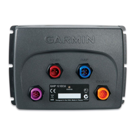
Garmin GHP 12 Handleiding voor installatie-instructies - Pagina 27
Blader online of download pdf Handleiding voor installatie-instructies voor {categorie_naam} Garmin GHP 12. Garmin GHP 12 32 pagina's. Drive unit and rudder feedback unit wiring reference
Ook voor Garmin GHP 12: Referentiehandleiding (2 pagina's)

Category
Steering System Setup >
Drive Unit Class > Other
Steering System Setup >
Drive Unit Class > Other
Steering System Setup >
Drive Unit Class > Other >
Advanced Drive Unit Tuning
Steering System Setup >
Drive Unit Class > Other >
Advanced Drive Unit Tuning
Steering System Setup >
Rudder Sensor Setup
Steering System Setup >
Rudder Sensor Setup
Steering System Setup >
Rudder Sensor Setup
Steering System Setup >
Rudder Sensor Setup
NOTE: Advanced configuration settings are available when using Dealer Mode
the GHP 12. See the configuration section of the GHC 10 Owner's Manual for more information.
Error and Warning Messages
Error Message
ECU voltage is low
No rudder position feedback
sensor detected
Rudder position data is
invalid.
Autopilot is not receiving
navigation data. Autopilot
placed in heading hold.
Connection with autopilot
lost
Lost wind data
Low GHC supply voltage
GHP 12 Installation Instructions
Setting
Description
Clutch Voltage
Only applicable if the Drive Unit Class has been set to "Other".
This setting tells the autopilot the voltage it should supply to the drive unit clutch. Refer to the
documentation supplied by the manufacturer of your drive unit to determine clutch voltage
specification.
An incorrect setting can cause damage to your drive unit clutch.
Generic Drive Unit
Only applicable if the Drive Unit Class has been set to "Other".
Tune
This initiates an automatic tuning procedure which determines an appropriate gain value for
the installed drive unit.
While performing this tune the autopilot will temporarily take control of the rudder.
Speed Tune
Only applicable if the Drive Unit Class has been set to "Other".
Allows you to adjusts how aggressively the drive unit responds to a given input
If this number is too high, the drive unit will overshoot and oscillate around its target position.
If this number is too low, the drive unit will respond slowly to a commanded change in position.
Error Tolerance Tune Only applicable if the Drive Unit Class has been set to "Other".
Allows you adjusts the amount of acceptable rudder position error
If this number is too high, a large amount of rudder position error will be allowed, and could
negatively affect the course during heading hold.
If the number is too low, the drive unit will attempt to eliminate small errors, causing excess
power consumption.
Max Port Angle
Allows you to enter the angle at which your rudder turns furthest port.
Max Starboard Angle Allows you to enter the angle at which your rudder turns furthest starboard.
Calibrate Rudder
Initiates a procedure which establishes the maximum range of movement of the rudder and
Sensor
calibrates the rudder sensor.
If an error appears during the calibration, the rudder feedback sensor has likely reached its
limit. Make sure the feedback sensor has been correctly installed. If the problem persists,
bypass this error by moving the rudder to the farthest position that does not report an error.
Calibrate Rudder
Initiates a procedure which establishes the center position of the rudder.
Center
Use this calibration if the on-screen rudder position indicator does not match the true rudder
center on your boat.
Cause
The ECU supply voltage goes below 10 Vdc for longer than 6 seconds.
The autopilot can't detect a rudder feedback device or valid rudder position.
The autopilot loses valid rudder position feedback data.
The autopilot is no longer receiving valid navigation data while performing a
Route-To.
This message will also be shown if navigation is stopped on a chartplotter
prior to disengaging the autopilot.
The GHC lost connection with CCU.
The autopilot is no longer receiving valid wind data.
The supply voltage level is below the value specified in the low voltage alarm
menu.
(page
19). Other settings are available during normal operation of
autopilot action
• Alarm sounds for 5 seconds
• Continues in normal operation
• Alarm sounds for 5 seconds
• Drive unit is disabled
• Autopilot transitions to Standby
• Alarm sounds for 5 seconds
• Drive unit is disabled
• Autopilot transitions to Standby
• Alarm sounds for 5 seconds
• Autopilot transitions to heading hold
N/A
• Alarm sounds for 5 seconds
• Autopilot transitions to heading hold
N/A
(page
21).
(page
21).
27
