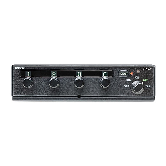
Garmin GTX 320 Installatiehandleiding - Pagina 18
Blader online of download pdf Installatiehandleiding voor {categorie_naam} Garmin GTX 320. Garmin GTX 320 43 pagina's. Garmin gtx 320/320a transponder installation manual
Ook voor Garmin GTX 320: Onderhoudshandleiding (24 pagina's), Handleiding voor piloten (4 pagina's), Installatiehandleiding (37 pagina's)

2.6 Check Existing Coax and Antenna Before Using a GTX 320/320A Adapter in an
Existing Installation
Before using a Narco or Bendix/King Adapter to install a GTX 320/320A into an existing
installation, the RF coaxial cable, its connectors, and the antenna must be checked to ensure the
following:
There must be no corrosion or damage on the coax or its RF connectors that would adversely affect
operation.
The RF attenuation of the coax from the installation rack to the antenna must not exceed 1.5 dB at
1090 MHz.
The antenna must not have corrosion, damage, or loose connections.
2.7 Installation Using Existing Narco AT 150 Installation Rack
The GTX 320 and GTX 320A can be used with an existing NARCO AT 150 Installation Rack by using the
NARCO AT 150 Installation Adapter (P/N 011-00292-00). See figure B6 for the NARCO AT 150 Adapter
assembly drawing.
GTX 320 units that are at Mod Level 1 must use the Mod Level 1 NARCO Installation Adapter.
After Mod Level 1, the GTX 320 sits 0.17" (4.3 mm) closer to the instrument panel. Also, when
installing the GTX 320 in an existing NARCO AT 150 rack (using the AT 150 Adapter) and when
the aircraft has a bus voltage of +28 VDC, make sure the +28 VDC dropping resistor is bypassed.
A.
Slide the adapter into the rack installation until the jackscrew mates with its nut.
B.
Turn the jack screw with a 3/32" Allen wrench until the adapter is secure.
C.
Looking at the bottom of the transponder, make sure the front lobe of the locking mechanism is in a
vertical position. This can be accomplished by using a 3/32" Allen wrench through the face plate.
D.
Slide the unit into the rack until the front lobe of the unit touches the rack. Guide pins on the back
plate will help properly align the unit in the rack.
E.
Turn the Allen wrench clockwise until unit is secured in the rack. Continue turning until tight. Do
not overtighten the screw.
F.
To remove the unit from the rack turn the 3/32" Allen wrench counterclockwise until it disengages
from the rack.
Page 2-8
Rev M
CAUTION
NOTES
GTX 320/320A Installation Manual
190-00133-01
