Indesit TIL641 Servicehandleiding - Pagina 6
Blader online of download pdf Servicehandleiding voor {categorie_naam} Indesit TIL641. Indesit TIL641 29 pagina's. Hobs 2006

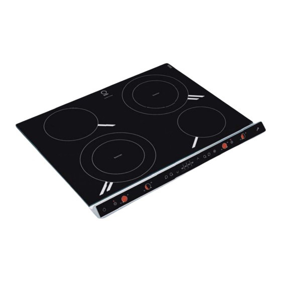
Cooking zones technical description
The induction system is the fastest known cooking
procedure.
Unlike traditional hotplates, in this case the cooking
zone itself does not heat up: the heat is generated
directly inside the pan, which must have a ferrous
magnetic base.
COOKTOPS
Cooking zone
Right-rear
Right-front
Left-front
Left-rear
Total maximum power
Single-phase connection
The Hob is equipped with power cord already con-
nected and prearranged for connection to a single-
phase power supply. Connect the wires according
to the following table and diagrams:
Other types of connection
If the electrical system complies with one of the
following characteristics:
Mains voltage, type and frequency
380V + N ~ 50 Hz
230V 3 ~ 50 Hz
380V + 2N ~ 50 Hz
Connect the wires according to the following table
and diagrams:
Service Manual
Hobs - 2006
TIL 642
Power
ID 2400 W – B 3000 W
I 1200 W – 600 W *
ID 2400 W – B 3000 W
I 1200 W – 600 W *
7200 W
Key:
I =
single induction cooking zone
ID =
double induction cooking zone
B =
booster: power of the cooking zone can be
boosted to 3000 W
* =
maximum power is restricted to 600 W as
long as the booster is active in the relative rear
cooking zone (see Start-up and use).
Mains voltage,
Power cord
type and frequency
230V 1+N ~
50 Hz
Mains voltage,
Power cord
type and frequency
400V - 2+N ~
50 Hz
230V 3 ~
50Hz
400V - 2+2N ~
50 Hz
Edition
2006.03.13
G
Wires connection
: yellow/green;
N: the 2 blue wires
together
k
L: brown with blac
Wires connection
: yellow/green;
N: the 2 blue wires
together
L1: black
L2: brawn
: yellow/green;
N1: blue
N2: blue
L1: black
L2: brown
Language
English
B
6
