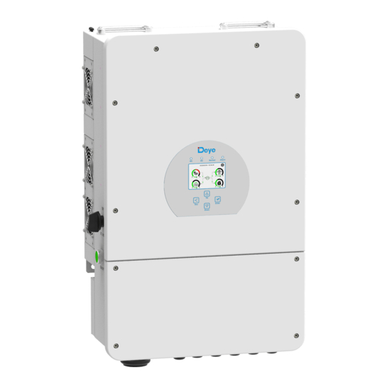
Deye SUN-5K-SG01LP1-US Gebruikershandleiding - Pagina 8
Blader online of download pdf Gebruikershandleiding voor {categorie_naam} Deye SUN-5K-SG01LP1-US. Deye SUN-5K-SG01LP1-US 20 pagina's. Hybrid inverter

Be sure that AC power source is disconnected before attempting to wire it
to the unit.
3. Then,insert AC output wires according to polarities indicated on the terminal block and
tighten terminal. Be sure to connect corresponding N wires and PE wires to related
terminals as well.
4. Make sure the wires are securely connected.
5. Appliances such as air conditioner are required at least 2-3 minutes to restart because it
is required to have enough time to balance refrigerant gas inside of circuit.If a power
shortage occurs and recovers in short time,it will cause damage to your connected
appliances.To prevent this kind of damage,please check manufacturer of air conditioner
if it is equipped with time-delay function before installation.Otherwise,this inverter will
trigger overload fault and cut off output to protect your appliance but sometimes it still
causes internal damage to the air conditioner
3.5 PV Connection
Before connecting to PV modules,please install a separately DC circuit breaker between
inverter and PV modules.It is very important for system safety and efficient operation to
use appropriate cable for PV module connection.To reduce risk of injury,please use the
proper recommended cable size as below.
Model
Wire Size
5/6/7.6/8KW
12AWG
Chart 3-4 Cable size
To avoid any malfunction, do not connect any PV modules with possible
current leakage to the inverter. For example, grounded PV modules will
cause current leakage to the inverter. When using PV modules, please be
sure NO grounding.
It is requested to use PV junction box with surge protection. Otherwise,it
will cause damage on inverter when lightning occurs on PV modules.
2
Cable(mm )
Torque value(max)
4
1.2Nm
- 11 -
3.5.1 PV Module Selection:
When selecting proper PV modules, please be sure to consider below parameters:
1) Open circuit Voltage (Voc) of PV modules not exceeds max. PV array open circuit
voltage of inverter.
2) Open circuit Voltage (Voc) of PV modules should be higher than min. start voltage.
Inverter Model
PV Input Voltage
PV Array MPPT Voltage Range
No. of MPP Trackers
No. of Strings per MPP Tracker
Chart 3-5
3.5.2 PV Module Wire Connection:
Please follow below steps to implement PV module connection:
1. Remove insulation sleeve 10 mm for positive and negative conductors.
2. Suggest to put bootlace ferrules on the end of positive and negative wires with a proper
crimping tool.
3. Check correct polarity of wire connection from PV modules and PV input connectors.
Then, connect positive pole (+) of connection wire to positive pole (+) of PV input
connector. Connect negative pole (-) of connection wire to negative pole(-)of PV input
connector.Close the switch and make sure the wires are tightly fixed.
5KW
6KW
7.6KW
8KW
370V(100V~500V)
125Vdc-425Vdc
2
1+1
2+1
2+2
- 12 -
