DeZURIK
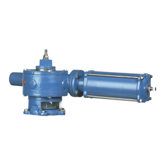
Cylinder Operated G-Series Actuator
Changing Mounting Positions
5. Remove the four screws that hold the wrenching nut to the gear sector, then remove the stud
locknut, spring washers and the wrenching nut with the keys.
6. Scribe corresponding lines on the actuator cover and housing, then remove the cover screws
and cover from the top of the actuator.
7. Mark which teeth of the rack and gear are engaged, and lift the gear sector out of the actuator.
8. Remove the screws fastening the adapter to the valve.
9. Remove the screws fastening the actuator housing to the adapter.
10. Rotate the adapter on the valve and the actuator on the adapter until the holes line up and the
actuator is in the desired position. Replace all of the screws.
11. Note the tooth that was marked on the gear sector and count clockwise five teeth on the size 16
actuator. This is the tooth that will engage with the marked tooth on the rack. Install the gear
sector using the new tooth engagement, and be sure the keyways in the gear sector match the
keyways in the plug stem.
12. Set a new cover gasket on the housing, then install the top cover on the housing, making sure
the scribe marks line up.
13. Hold the keys in position and slide the wrenching nut over the plug stud, then guide the keys
into the gear sector and stem slots.
14. Install the four screws fastening the wrenching nut to the gear sector.
15. Place the spring washers on the plug stud as shown in Figure 5.
16. Screw the lock nut down the plug stud until it is tight and the spring washers are completely
compressed, then back the nut off one full turn.
17. Tighten the #2 lockscrews, and then the #1 lockscrews to hold the keys in place.
18. Adjust the position stops—see "Position Stops" section.
Troubleshooting
Condition
Actuator closes to wrong
position
Actuator opens to wrong
position
Actuator will not fully operate
valve
Actuator rotates wrong
direction
D10022
(Continued)
Possible Cause
Closed position stop is set
incorrectly
Open position stop is set
incorrectly
Cylinder pressure is low
Piston seal in cylinder is leaking
Pipeline obstruction in valve is
preventing closure
Air connections to cylinder are
incorrect
Page 18
Corrective Action
Adjust closed position stop. See
Adjusting Position Stops section
Adjust open position stop. See
Adjusting Position Stops section
Increase cylinder pressure. Do
not exceed 100 psi (69 kPa).
Replace piston seal(s). See
Cylinder instructions.
Remove obstruction
Reverse air connections to
cylinder
August 2012

