DeZurik G-SERIES Handmatig - Pagina 6

Blader online of download pdf Handmatig voor {categorie_naam} DeZurik G-SERIES. DeZurik G-SERIES 17 pagina's. Lift, turn and reseat used on ptw & pfw tapered plug valves
Ook voor DeZurik G-SERIES: Instructie (7 pagina's), Handmatig (8 pagina's), Handmatig (17 pagina's), Handmatig (14 pagina's), Handmatig (12 pagina's), Handmatig (14 pagina's), Handmatig (16 pagina's), Instructie (19 pagina's), Gebruiksaanwijzing (13 pagina's), Handmatig (9 pagina's)
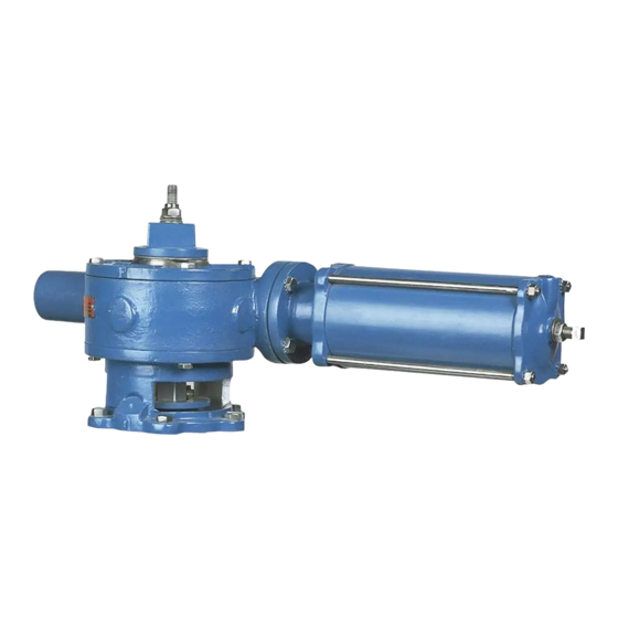
DeZurik G-SERIES Handmatig
DeZURIK

Stop Adjustments

The open and closed position stops prevent the valve plug from rotating beyond the optimum open and
shutoff positions.
If the actuator is factory-mounted on the valve, the stops are preset, and do not require further
adjustment. If the actuator is not factory mounted on the valve, or if the actuator has been removed, the
stops will require adjustment as described below; also refer to the Valve Instructions for specific closed
position requirements for the valve.
Valves can be mounted with Direct or Reverse pressure.
Direct Pressure - When the higher pressure is at the end opposite the seat. See Figure 3.
Reverse Pressure - When the higher pressure is at the seat end of the valve. See Figure 3.

To Adjust the Closed Position Stop

See Figure 5 for stop Identification.
To adjust the closed position stop: (see Figure 5 for stop identification) Adjusting
stops with flow in the pipeline can allow the valve to close causing personal
injury and damaging the flow system.
Shut down the flow and relieve pipeline pressure before making stop adjustments
1. Discontinue flow and relieve pipeline pressure.
2. Close the valve.
3. Loosen the nut on the closed position screw, and back out the screw about two turns.
4. Turn the handwheel, chainwheel or 2" wrenching square operator until the specified Actuator
Input Torque from Table A is reached.
5. While maintaining the Actuator Input Torque from Table A, turn the closed position screw
clockwise until resistance is felt from the screw contacting the gear (B1C).
6. Prevent the screw from turning and tighten the nut against housing (B1A).
7. Pipeline flow may now be restored.
D10456
Figure 3— Pressure Direction
Page 6
August 2012