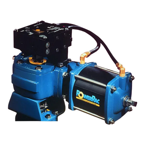
DeZurik POWERRAC R1 Gebruiksaanwijzing - Pagina 15
Blader online of download pdf Gebruiksaanwijzing voor {categorie_naam} DeZurik POWERRAC R1. DeZurik POWERRAC R1 20 pagina's. Spring-return actuator used on 1/2-3" pec eccentric valves

Changing Actuator from Spring-Return to Double-Acting
Changing the actuator from spring-return to double acting requires a different cylinder assembly, which
can be ordered from DeZURIK.
1. If the actuator is on a valve, remove the actuator from the valve. See "Removing Actuator"
section.
2. Disassemble the actuator. See "Actuator Disassembly" section.
3. Assemble the actuator as described in the "Double-Acting Actuator Reassembly" section of the
instructions furnished with the double acting cylinder.
4. Replace the actuator on the valve as described in the "Mounting Actuator on Valve" section of
the instructions furnished with the double acting cylinder.
Reversing Spring Action
1. If the actuator is on a valve, remove the actuator from the valve. See "Removing Actuator"
section.
2. Disassemble the actuator. See "Actuator Disassembly" section.
3. Assemble the actuator as described in the "Actuator Reassembly" section, following the
instructions for the desired spring action.
4. Replace the actuator on the valve. See "Mounting Actuator" section.
Changing Mounting Position
The actuator may be mounted in any of four positions on the valve. The mounting position may be
changed as follows:
1. Remove the actuator from the valve as described in the "Removing Actuator" section.
2. Replace the actuator on the valve as described in the "Mounting Actuator" section.
Lockable Model
The R1 PowerRac® Single Cylinder Spring-Return Actuator is available as a lockable model that allows
the actuator to be locked in either the open or closed position. The lockable model is identified by PRL
in the catalog characteristic.
As shown in Figures 9 and 10, the lockable model has a notched gear (B8) and an enlarged housing
(B1) that includes two lock screws (B64) and two jam nuts (B65). A lockout cover assembly (B60) is
also included.
The gear (B8) will be damaged if either of the stop screws is placed in an intermediate
position between the unlocked and locked positions. The two lock screws (B64) must be in
either the unlocked or the locked position as described in the following sections.
November 2020
Page 15
DeZURIK
D10389
