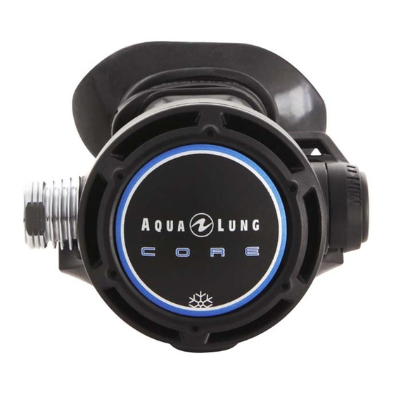
Aqua Lung CORE Servicehandleiding - Pagina 8
Blader online of download pdf Servicehandleiding voor {categorie_naam} Aqua Lung CORE. Aqua Lung CORE 18 pagina's.

- 1. Table of Contents
- 2. Copyright
- 3. Introduction
- 4. Warnings, Attention, Notes
- 5. Maintenance
- 6. General Instructions
- 7. General Conventions
- 8. Disassembly Procedure
- 9. Reassembly Procedure
- 10. Controle Final
- 11. Final Reassembly
- 12. Appendix
- 13. Procedure a - Cleaning and Lubricating
- 14. Maintenance Notes
REASSEMBLY PROCEDURE
1.
If the exhaust valve (129174) has been removed, pass
the valve tail through the case hole (129931 or 129932),
from outside and pull gently until the notch is inside the
case. If it is a new exhaust valve, one installed, cut off any
excess tail leaving about 5mm.
2.
Place the exhaust tee
(129908) on both case
notches
(129931
129932) and pull on its
low part to clip it.
3.
Fit a new O-ring (AP2041) in the shuttle valve groove
(AP2036). Insert a new rubber seating (129638) in the
shuttle valve. With a brush, lubricate the shuttle valve tail
(O-ring side).
4.
Insert the spring (AP2021) in the counter balance cylinder
(129784). Guide carefully the shuttle valve tail (AP2036)
inside the spring and insert it in the counter balance
cylinder.
5.
If the lever (129178) has
been removed, place it again,
take care to install it at the
same side as the valve
spindle punch (129146).
nd
Service Manual Core 2
Rev. 05/2015
or
stage
6.
Fit
a
new
lubricated
(124706) on the valve spindle
(129146).
7.
Fit a new lubricated O-ring (124703) on
the adjusting screw (129162).
8.
Fit a new lubricated O-ring (444243) on the
valve seat (AP2033).
Insert the valve seat, thread first, inside the valve spindle
(129146), thread side, and push until stop.
9.
Insert the assembled shuttle valve in the valve spindle
(129146), not threaded side. Shuttle valve notches should
be at the opposite side of the lever.
With the plastic side of the tool (116236), push on the
counter balance cylinder (129784) and check that the
lever raise.
10. Insert
the
adjusting
(129162) in the valve spindle
(129146), not threaded side.
There should be a tension on
the lever (due to the spring).
Using a 4 mm Allen key, screw
the adjusting screw until the
tension pin hole is clear.
nd
Service Manual Core 2
stage
O-ring
screw
Clear hole
8
