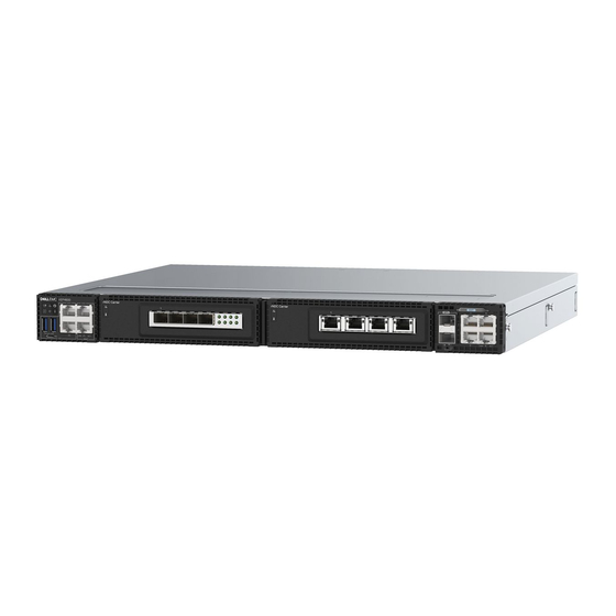
Dell VEP4600 Installatiehandleiding - Pagina 11
Blader online of download pdf Installatiehandleiding voor {categorie_naam} Dell VEP4600. Dell VEP4600 40 pagina's.
Ook voor Dell VEP4600: Installatiehandleiding (23 pagina's), Installatiehandleiding (40 pagina's)

Figure 5. rNDC front panel LED call-outs
Table 4. Expansion card LEDs
LED
1.) System LED
2.) Temperature LED
Pre-requisites
NOTE:
For detailed installation instructions, see
The following is a list of components required for successful platform installation:
● VEP4600 platform
● AC country- and regional-specific cables to connect the AC power source to each of the platforms' AC power supplies
● Two-post rail kit mounting brackets for rack installation, included
● Screws for rack installation
● #1 and #2 Phillips screwdrivers, not included
● M2 Philips drive screwdriver, not included
● Ground cable screws (included) for L-bracket—order separately
● M3 ground lug assembly kit screw, depending on your platform
● Copper/fiber cables
Other optional components are:
● UL-certified ground lug assembly kit with bracket
● Extra mounting brackets for the 4-post mount
● Extra power supply unit
● Extra fan module
Description
● Off—Card is off
● Solid green—Normal operation
● Solid yellow—Citical card error
● Flashing green—Booting
● Flashing yellow—Noncritical card error
● Off—Card is off
● Solid green—Normal temperature operation
● Solid yellow—Temperature is at the limit
● Flashing yellow—Temperature is over the limit
Site preparations
and
VEP4600
installation.
VEP4600 platform
11
