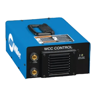
Miller WCC Control Gebruikershandleiding - Pagina 17
Blader online of download pdf Gebruikershandleiding voor {categorie_naam} Miller WCC Control. Miller WCC Control 28 pagina's. Weld cable communication control

3-4. WCC (Weld Cable Control) Applications
.
The WCC Control must be used with a Suitcase X-TREME WCC wire feeder, and a XMT 350 or XMT 456 welding power source.
3-5. Associating Wire Feeder To WCC Control
Quick Setup Guide:
1
Pull trigger on gun.
2
Do not strike an arc.
3
Decimal points on feeder voltmeter will blink.
4
When decimal points stop blinking and a voltage is displayed, the feeder and WCC Control are associated.
5
Use voltage control on feeder to adjust weld voltage.
6
Voltmeter on feeder will alternate between preset voltage and open circuit voltage while idle. While welding the feeder will display the actual
weld voltage at the wire feeder.
.
See Section 3-6 for detailed equipment setup.
3-6. Equipment Setup
During WCC operation, preset weld voltage
and wire feed speed are set at the wire feeder
front panel.
Associating a WCC compatible wire feed-
er, WCC control and welding power
source:
1
On welding power source set Mode
Switch to V-SENSE FEEDER position.
2
On welding power source set
Panel/Remote Control Switch to
REMOTE position (if applicable).
3
On feeder set CC/CV switch to CV. The
feeder will not associate with WCC
Control if the feeder is set to CC.
4
After connecting wire feeder to WCC
Control and WCC Control to welding
power source (see Section 3-3) turn on
wire feeder and welding power source.
5
The welding power source voltage
display alternates between preset
voltage (set at the welding power
source) and open circuit voltage. The
wire feeder voltage display will alternate
between three dashes and open circuit
voltage.
6
For the wire feeder to control the
welding power source the wire feed
must be associated to the WCC control.
If wire feeder is not associated to the
WCC control, the wire feeder will try to
3-7. Connecting Weld Cable
associate to the WCC control when the
trigger is pulled. To associate the wire
feeder to the WCC control, pull and hold
the welding gun trigger − DO NOT
STRIKE AN ARC. While the association
process is taking place the decimal
points on the wire feeder voltage display
will blink. When associated, the decimal
points stop blinking and preset voltage
is displayed. Release trigger on welding
gun after preset voltage is displayed.
The association process may take up to
five seconds to complete.
7
Once association is complete the
voltage display on the wire feeder will
alternate between preset voltage and
open circuit voltage. The voltage display
on the welding power source will
alternate between preset voltage (set by
the wire feeder) and open circuit
voltage. Preset voltages between the
wire feeder and the welding power
source should be within 0.5 volt of each
other.
8
While adjusting the voltage control on
the feeder the voltage display will show
only preset voltage. Ten seconds after
the preset voltage has been set the
display will alternate between preset
voltage and open circuit voltage.
9
While welding the welding power source
displays weld voltage at the studs. The
1
wire feeder displays weld voltage at wire
feeder.
10 While welding, due to voltage drops in
the weld cable, voltage displays at wire
feeder and welding power source will
not match. The preset voltage at wire
feeder must be set to a higher value to
compensate for voltage drop of the weld
cable. For example, if welding voltage of
18 volts is desired at the wire feeder
and there is a 4 volt drop in the weld
cable, the preset voltage at the wire
feeder should be 22 volts. (18V + 4V =
22V).
11 Once wire feeder and WCC control are
associated, they will stay associated
until either the wire feeder or welding
power source is turned off. The wire
feeder can lose power for up to ten
seconds and still recover its association
with the WCC control. This is for
situations where the wire feeder may
momentarily lose power due to a
prolonged short circuit condition in the
welding process.
12 If the CC/CV switch on the feeder is
changed to CC the feeder will lose it's
association with the WCC Control. To
re-establish the association, set switch
to CV and restart the association
process.
!
Turn Off wire feeder and
welding power source. Stop
engine on welding
generator.
1
WCC Control
2
User-Supplied Weld Cable
Insert male connector into female
connector and turn clockwise until
tight.
2
OM-247 506 Page 13
247 894-A
