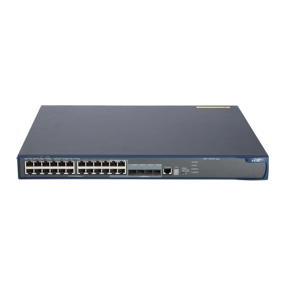
HP 5120-24G-PoE+ EI Configuratiehandleiding - Pagina 15
Blader online of download pdf Configuratiehandleiding voor {categorie_naam} HP 5120-24G-PoE+ EI. HP 5120-24G-PoE+ EI 39 pagina's. Hp 5120 ei switch series
Ook voor HP 5120-24G-PoE+ EI: Gegevensblad (17 pagina's)

Configuring IRF
Read the configuration restrictions and guidelines carefully when you connect and set up an IRF fabric.
General restrictions and configuration guidelines
This section describes the restrictions and configuration guidelines you must follow.
Software requirements
All IRF member switches must run the same system software image version.
IRF link redundancy
The switch supports up to two physical ports for an IRF port, and these two ports must be located on the
same interface card.
IRF physical port restrictions and cabling requirements
Candidate IRF physical ports include 10-GE ports on expansion interface cards. To use IRF, purchase at
least one interface card. The following are the interface cards available for IRF connections:
LSPM1XP1P (JD361B)
•
•
LSPM1XP2P (JD359B)
LSPM1CX2P (JD360B)
•
•
LSPM2SP2P (JD368B)
LSPM1XGT2P (JG535A)
•
For long-distance IRF connections, use XFP or SFP+ transceiver modules and fibers. For short-distance IRF
connections, use 10 GE Ethernet twisted pairs, CX4 or SFP+ cables. For more information about
transceiver modules available for an interface card, see the interface card user guide.
For more information about transceiver modules, see HP A-Series Switches Transceiver Modules User
Guide.
The SFP+ modules and SFP+ cables available for the switch are subject to change over time. For the most
up-to-date list of SFP+ modules and cables, contact HP technical support or marketing staff.
IRF port binding restrictions
Facing the rear panel, make sure the physical ports bound to IRF port 1 is on the left of the physical ports
bound to IRF port 2.
Physical ports of an IRF port must be on the same interface card.
MAD
•
Configure at least one MAD mechanism for prompt IRF split detection and IRF fabric recovery.
11
