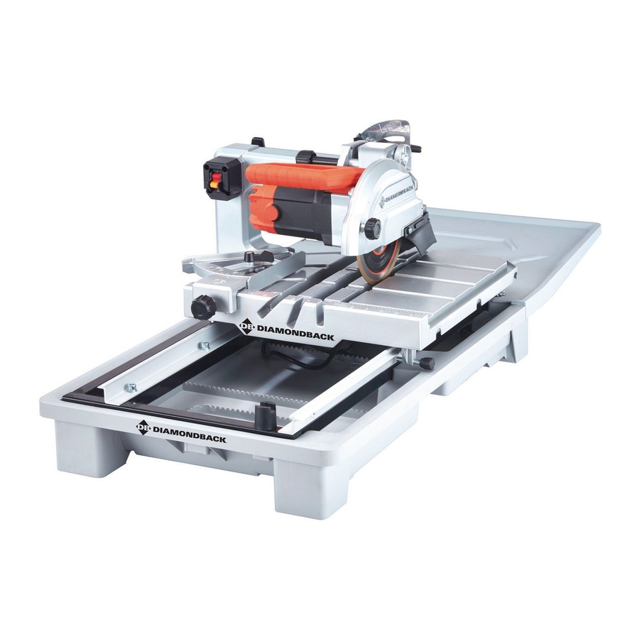
Diamondback 64683 Gebruiksaanwijzing & veiligheidsinstructies - Pagina 8
Blader online of download pdf Gebruiksaanwijzing & veiligheidsinstructies voor {categorie_naam} Diamondback 64683. Diamondback 64683 20 pagina's. 7" heavy-duty tile saw with sliding table

aSSEMBLy
tO prEVEnt SEriOuS inJury FrOM acciDEntaL OpEratiOn:
turn the power Switch of the tool off, remove the Safety Key, and unplug the tool
from its electrical outlet before performing any procedure in this section.
note: For additional information regarding the parts listed in the following pages,
refer to the Assembly Diagram near the end of this manual.
installing Motor Head
1. Place three Screw Sleeves (128)
into top mounting holes on Water
Tray Frame (120) as shown.
2. Align the holes in the Motor Head
Assembly with the corresponding mounting
holes on the top of the Water Tray Frame.
3. Insert three M10 x 6 0 Socket Head Cap
Screws (131) through three Spring
Washers (130), Flat Washers (129),
the Motor Head Assembly, and the
Water Tray Frame. Secure using M10
Lock Nuts (127). Finger tighten.
4. Place two Screw Sleeves (128)
into side mounting holes on Water
Tray Frame as shown.
5. Insert two M10 x 6 0 Socket Head Cap
Screws (131) through two Spring Washers (130),
Flat Washers (129), the Motor Head Assembly,
and then into side mounting holes on the Water
Tray Frame. Secure using M10 Lock Nuts (127).
6. Tighten three previously installed M10 x 6 0
Socket Head Cap Screws securely.
7. With assistance, place the completed
Motor Head / W ater Tray Frame
assembly on the Water Tray (77).
Page 8
M10 x 6 0
cap Screw
Spring
Washer
Flat
Washer
Lock nut
M10 x 6 0
cap Screw
For technical questions, please call 1-888-866-5797.
M10
Screw
Sleeve
Water tray Frame
Flat
Washer
Spring
Washer
Motor Head installation
Motor
Head
assembly
Water
tray
Frame
Screw
Sleeve
M10 Lock nut
Item 64683
