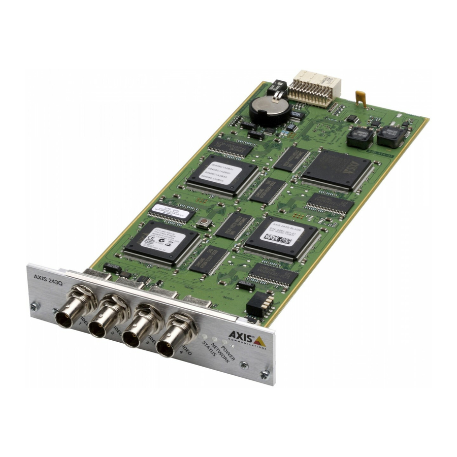
Axis 240Q Blade Installatiehandleiding - Pagina 6
Blader online of download pdf Installatiehandleiding voor {categorie_naam} Axis 240Q Blade. Axis 240Q Blade 9 pagina's. Video server
Ook voor Axis 240Q Blade: Specificaties (6 pagina's), Specificaties (2 pagina's), Specificaties (2 pagina's), Gegevensblad (2 pagina's), Gegevensblad (2 pagina's)

6
AXIS 240Q Blade - Rack Solution Installation Guide
The I/O Terminal Block
The AXIS 240Q Blade Video Server connects to an I/O terminal block used for transmitting
data over multi-drop communication lines:
• RS-485 Pan/Tilt devices
• RS-232 Pan/Tilt devices
• External triggering (typically associated with CCTV equipment)
The AXIS 240Q Blade supports several Pan/Tilt device drivers, which are available from
the Axis Web site at www.axis.com
Connector Pinout
The pinout for the I/O Terminal Block and the signaling details for each pin:
Pin
Function
1
RS-232
2
RS-232
3
RS-232
4
RS-232
5
GND
6
RS-232
7
RS-232
8
RS-232
9
RS-232
10
GND
11
n/a
12
n/a
13
n/a
14
n/a
For compatible replacement connectors, contact http://www.phoenixcontact.com, quoting:
MC1.5/14-ST-3.81 (art. no. 1803691).
For further information, please refer to the Unit Connections section in the AXIS 240Q
User's Manual.
Description
Pin
RI
15
CTS
16
RTS
17
DSR
18
19
DTR
20
TXD
21
RXD
22
CD
23
24
25
26
27
28
Function
Description
RS-485 - A
A half-duplex RS-485 interface for con-
(non-inverting)
trolling auxiliary equipment, e.g. PTZ
devices.
RS-485 - B
(inverting)
Transistor Output 4
With a maximum load of 100mA and
maximum voltage of 24V DC, this out-
put has an open-collector NPN transis-
tor with the emitter connected to GND.
To use with an external relay, a diode
must be connected in parallel with the
load, for protection against voltage
transients.
GND
Transistor Output 3
See Transistor Output 4 above.
Transistor Output 2
See Transistor Output 4 above.
GND
Transistor Output 1
See Transistor Output 4 above.
Digital Input 4
Connect to GND to activate, or leave
floating (or unconnected) to deactivate
GND
Digital Input 3
See Digital Input 4 above.
Digital Input 2
See Digital Input 4 above.
GND
Digital Input 1
See Digital Input 4 above.
