HTC CM-2018 Handmatig - Pagina 2
Blader online of download pdf Handmatig voor {categorie_naam} HTC CM-2018. HTC CM-2018 2 pagina's. Digital ac/dc clamp meter
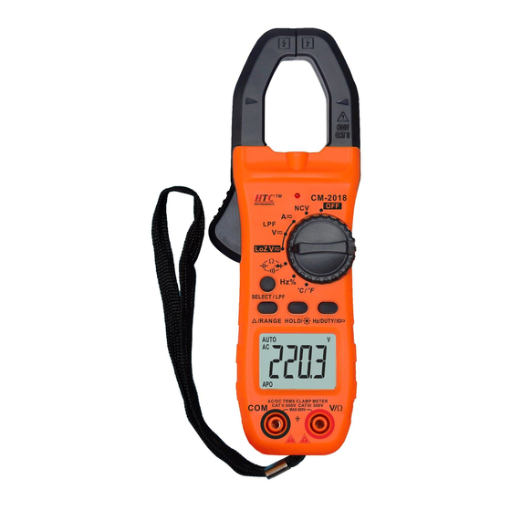
(8)Display: Shows the value and unit measured by the meter.
Serial
Function
number
Auto power off display symbol, high voltage alarm symbol,
1
APO
MAX-MIN
MAX-MIN invalid.
2
△
Clear or Relative (REL) mode is enabled.
3
HOLD
The data hold function is enabled.
The sign is displayed when the measurement result is
4
-
negative.
The multimeter is in the DC voltage or DC current
5
DC
measurement state.
The multimeter is in AC voltage or AC current measurement
6
AC
state.
7
AUTO
The multimeter is in auto-range mode.
8
Variable frequency voltage measurement.
9
Diode measurement.
10
The connectivity buzzer is activated.
Triode (for triode amplification measurements)
hFE
Nano farad, micro farad.
Milli volt, volt (V).
nF, μF
Micro ampere, milli ampere, ampere (A).
mV, V
Percentage (for duty cycle factor measurements), Celsius
uA, mA, A
temperature, Fahrenheit temperature.
11
%, ℃, °F
Non-contact AC voltage detection display symbols.
NCV
Meg ohm, kilohms, ohms.
MΩ, kΩ, Ω
Hertz, kilohertz, mega hertz
Hz, kHz, MHz
The battery is low. WARNING: To avoid incorrect readings
that could result in electric shock or personal injury, replace
the batteries as soon as the battery indicator appears.
(9)V/Ω input terminal: measurement of input voltage, resistance, diode, capacitance, frequency,
temperature, etc. "+" input positive (insert the red test lead).
COM common ground input terminal: negative side of the measurement input (insert the black
test lead).
(10)Anti-drop wristband.
4-2. AC/DC Voltage Measurement
(1)Turn the function switch to the
range position, then insert the red test
lead into the "VΩ" input terminal and the black test lead into the "COM"
terminal.
(2)The default is DC voltage measurement, press "SELECT/LPF" to select DC
or AC measurement method.
(3)When the test lea is connected across the circuit under test, and the voltage
and polarity of the point to which the red test is connected are displayed on
the screen at the same time.
(4)When measuring AC voltage, press Hz/DUTY to display the frequency and
duty cycle of the voltage being measured.
(5)Press and hold the "SELECT/LPF" key to select the "
" low-pass filter for AC voltage
measurement.
Caution.
(1)There may exist some residual figures for small ranges before testing, which do not affect the
accuracy of the measurement.
(2)The input voltage must not exceed the limit, and if it does, there is a risk of damage to the
instrument circuitry.
(3)When measuring high voltage circuits, the human body must take care to avoid touching the
high voltage circuits.
(4)After completing all measurement operations, disconnect the test leads from all circuits.
4-3. True RMS Voltage Measurement of Variable Frequency Voltage
(1)Press "SELECT/LPF" for more than 2 seconds while measuring voltage to enter the "
low-pass filter function.
(2)Selecting this filter function will intercept voltages above 1 kHz, enabling measurement of
composite sinusoidal signals generated by inverters and inverter motors.
(3)When the test lead touches the test point, and the voltage of the two points connected to the
test lead is displayed on the screen.
Caution.
(1) Manual range mode, such as LCD display: "OL", indicating that the range has exceeded the
range, the range switch must be turned to a higher gear.
(2) The measurement voltage must not exceed ACV 600V, if over, there is a risk of damage to the
instrument circuit.
(3) When measuring high-voltage circuits, always take care to avoid touching high-voltage circuits.
(4) When the measured voltage is over 610V, the built-in buzzer of the instrument will sound to alert
the operator to use with Caution.
4-4. Low Impedance Voltage Measurement
(1)Turn the function switch to "LoZ
" range position. the default is DC voltage
measurement, press the "SELECT/LPF" key to select DC or AC measurement mode.
(2)The test lead is connected across the circuit under test, and the voltage and polarity of the
point to which the red test lead is connected are displayed on the screen at the same time.
(3)When measuring AC voltage, press Hz/DUTY to display the frequency and
duty cycle of the voltage being measured.
(4)Press and hold the "SELECT/LPF" key to select the "
" low-pass filter for
AC voltage measurement.
Caution.
(1) Pay high attention to use this low impedance voltage measuring function for the
standard source devices when the output power is unknown, or long
measurements may damage the device under test.
4-5. AC/DC current measurement
(1)Turn the function switch to "
" range position. the default is DC current
measurement, press the "SELECT/LPF" key to select DC or AC measurement mode.
(2)The display may not return to zero due to the ambient magnetic field, please press "REL" to
clear the value to zero before measurement.
(3)Press and hold the trigger to open the clamp jaw, use the forceps to clamp the
conductor to be measured, and then slowly release the trigger until the
Meaning
forceps are completely closed.
(4)The reading shows the value of the current on the conductor under test. To
obtain the most accurate reading, the conductor must be placed through the
middle of the closed jaws.
Caution.
(1)The instrument uses Hall components to sense current, and Hall parts are a
sensitive device, in addition to magnetic sensitivity, temperature, mechanical
stress are sensitive to varying degrees, the impact will cause a short time
reading changes. Therefore, it will cause the phenomenon that the DC range reading does not
return to zero, it is necessary to press REL key to clear the zero after the measured reading to
be accurate.
(2)Open the jaws by pressing the trigger, grip the jaws on the conductor to be measured, then
slowly release the trigger until the jaws are completely closed. Determine if the conductor to
be measured is clamped in the center of the jaws. Only one conductor can be measured at a
time. if two or more conductors are measured at the same time, the measurement reading will
be incorrect. Not placed in the center of the jaws will produce ± 1.0% additional error in the
reading. The current value on the conductor
under test is displayed.
(3)In DC current measurement, if the reading is
positive, the direction of the current is from top
to bottom (top for the panel and bottom for the
bottom cover, the measuring meter is face up).
(4)The maximum test current is 800A. Long time
exceeding the rated current will damage the
instrument.
The following practices will make DC current
measurements more accurate.
① Turn off the current to the conductor to be measured. Press the trigger to open the jaws, clamp
the jaws on the conductor to be measured, then slowly release the trigger until the jaws are
completely closed to determine if the conductor to be measured is clamped in the center of the
jaws.
② Please press REL to clear the value to zero when the the reading to stabilize at
the minimum value.
③ Turn on the current of the conductor to be measured and read the value after
stabilization.
④ The current measurement function is advised to be operated between 0°C and
40°C, so that the results of the measurement will give a more accurate DC
current reading.
4-6. Resistance measurement
(1)Turn the function switch to "
"SELECT/LPF" key to select the Ω measurement method.
(2)Insert the red test lead into the "VΩ" input terminal and the black test lead into the "COM"
input terminal.
(3)Connect the test leads across the resistance under test and read the measured value.
Caution.
(1)When using the manual range measurement method, the switch should be set to the highest
gear if there is no prior concept of the resistance range to be measured.
(2)If the LCD shows "OL", it indicates that the range has been exceeded and must be adjusted up
a gear. When the measured resistance is more than 1MΩ, the reading takes a
few seconds to stabilize, which is normal when measuring high resistance.
(3)When the input is open circuit, the overload condition "OL" is displayed.
(4)When measuring in-line resistance, make sure that all power supplies to the
circuit under test are turned off and all capacitors are fully discharged.
(5)If there exists relatively large error in the measurement, it may be due to the
influence of other originals in the line or a potential at both ends of this
resistor.
(6)Do not input voltage at the resistance range.
4-7. Diode and continuity measurement
(1)Put the range on "
"
screen displays the symbol of
lead into the "V/Ω" jack. (Note that the polarity of the test lead is "+").
(2)Positive measurement: the red test lead is connected to the positive terminal of the diode
under test, the black test lead is connected to the negative terminal of the diode under test, the
reading is the approximate value of the positive voltage drop of the diode; For the silicon PN
junction, it shows 500 ~ 800 to confirm the normal value; If the diode under test is open or the
polarity is reversed, it shows "OL".
(3)Reverse measurement: the red test lead is connected to the negative terminal of the diode
under test, the black test lead is connected to the positive terminal of the diode under test, the
screen will show "OL". if the diode under test leaks or breaks down, it will show a certain
value.
(4)A complete diode test including forward and reverse direction measurements, if the
measurements do not match the above, the diode is damaged.
(5)Press the "SELECT/LPF" key to select the on-off measurement method. (the screen displays
the
symbol).
(6)Connect the test leads to the two points of the line to be tested, and if the built-in buzzer
sounds, the resistance value between the two points is lower than 50Ω.
Caution.
(1)It is forbidden to input voltage at the "
(2)When measuring online, make sure the power is off and all capacitors are discharged. Any
negative potential or AC signal will cause the buzzer to sound.
4-8. Capacitance measurement
(1) Turn the function switch to the "
"SELECT/LPF" key to select
(2) Insert the red test lead into the "VΩ" input terminal and the black test lead into
the "COM" terminal.
(3) Before measurement, if the display shows that it is not zero, press the "REL"
key once to clear the zero.
(4) Use the test leads to connect the corresponding polarity of the capacitor under
test (note that the polarity of the red test lead is "+") to the input of "COM" and
"VΩ", and the screen will show the capacitance.
Caution.
" range position and press the
", press the "SELECT/LPF" key, select the diode measurement (the
), insert the black test lead into the "COM" jack, the red test
" range to avoid damage to the meter.
" range position and press the
measurement.
(1)It is strictly forbidden to input voltage or current signals in the measuring capacity range.
(2)Before each test, if the display has readings, you must press the "REL" key once to clear the
value to zero to ensure the accuracy of the measurement.
(3)Capacitance range is only with the automatic range operation.
(4)The capacitor under test should be completely discharged to prevent damage to the meter.
4-9. Frequency, Duty cycle measurement
(1)Turn the function switch to the Hz range position, then insert the red test lead into the "VΩ"
input terminal and the black test lead into the "COM" terminal.
(2)Connect the test leads across the circuit under test and read the measured value.
(3)Press Hz/DUTY to toggle frequency and duty cycle measurement.
Caution.
(1)When the input exceeds 10Vrms, please operate in ACV range and press
Hz/DUTY to switch the frequency duty cycle measurement.
(2)In a noisy environment, it is best to use shielded cables when measuring
small signals.
(3)Do not touch high voltage circuits when measuring high voltage circuits.
(4)Input of voltage values higher than 250 V rms is prohibited in this range.
4-10. Temperature measurement
(1)Turn the function switch to ℃/℉ range position, then insert the cold end
(free end) of the thermocouple sensor's negative pole (black plug) into the
"COM" hole, the positive pole (red plug) into the "VΩ" jack, the working end (measuring
end) of the thermocouple is placed on top of or inside the object to be measured, then read the
temperature measurement value directly from the screen, press the "SELECT/LPF" key to
switch between ℃ or ℉. The working end (measuring end) of the thermocouple is placed
above or inside the object to be measured, then read the temperature
measurement value directly from the screen, and press "SELECT/LPF" to
switch ℃ or ℉.
Caution.
(1)The instrument should be kept away from high temperatures during
measurement, and the thermocouple temperature probe should be used within
the range specified for testing.
(2)Do not replace the temperature measurement sensor at will, otherwise the
measurement accuracy will not be guaranteed.
(3)It is strictly forbidden to enter voltage values in this range.
4-11. Non-contact AC voltage detection
Warning: This function is subject to different sources of external interference, false alarms may
occur, when using, the measurement results are for reference only.
(1)Put the function switch in the "NCV" position, when the line to be tested against the top of the
clamp head, the instrument induction voltage indicator light, buzzer issued a drop - drop -
drop alarm sound. Or insert the red test lead into the "VΩ" input terminal, the probe touches
the charged line (for narrow special test environment), there will be an audible
and visual alarm.
(2)NCV measurement results are displayed in 5 levels, 0~50mV display LO,
50~100mV/100~150mV/150~200mV/250mV and above display 1~4 '-'
characters respectively, accompanied by different rhythm buzzer sound.
Attention:
(1)Even if there is no indication, voltage may still be present. do not rely on a
non-contact voltage detector to determine if voltage is present on the wire.
(2)Detecting results may be affected by factors such as socket design, insulation
thickness and different types.
(3)When voltage is input to the input terminal of the instrument, the voltage sense indicator light
may also be on due to the presence of the induced voltage.
(4)External environmental sources of interference (such as flash, motor, etc.) may be misjudged.
4-12. Auto Power OFF
When the instrument stops using for about 15 minutes, the instrument will automatically power
off and enter the hibernation state; To restart the power, dial to OFF, turn the rotary dial to other
gears. press and hold the "SELECT/LPF" key, while turning on the power switch, the "APO"
symbol on the screen will disappear, and the automatic shutdown function will be canceled.
5. Trouble Shooting
If the meter does not work properly, please check the meter as following steps:
(If the problem is still not solved, please refer to repairing center or contact the local dealers.)
Fault
Solution
n Power not connected.
No display on LCD
n Replace the battery.
Symbols appear
n Replace the battery.
n Replace the battery.
Large display error
6. Instrument Maintenance
The meter is a precision instrument, random changes to the circuit should be avoided.
(1)Please pay attention to keep the meter away from the water, dust and shock.
(2)The meter is not suitable for storage and use in high temperature and high humidity,
flammable and explosive and strong magnetic field environment.
(3)Use a damp cloth and a mild detergent to clean the exterior of the instrument, do not use
abrasives and strong solvents, like alcohol.
(4)To avoid leakage damage, please take out the battery if the meter will not be used for a long
time.
Caution.
(1)When the screen shows the symbol " ", replace the battery, step 3 below.
(2)Unscrew the screws securing the battery cover and withdraw it.
(3)Remove the 1.5V batteries and replace them with two new batteries, although any standard
1.5V batteries can be used, but to extend the use time, it is best to use alkaline batteries.
(4)Put on the battery cover and tighten the screws.
n T h e sp ecification s are su b ject to ch an ges w ith ou t p rior n otice.
n T h e con ten t of th is m an u al is regard ed as correct. If u sers fin d ou t an y
m istak es or om ission s, p lease k in d ly con tact th e m an u factu rer.
n T h e m an u factu rer w ill n ot b e resp on sib le for accid en ts an d d am age cau sed
b y im p rop er op eration s.
n Th e fu n ctio n s d escrib ed in th is U ser M an u al sh all n o t b e co n sid ered as th e
re aso n fo r any sp e cial u sage .
EN-2018_V0.0