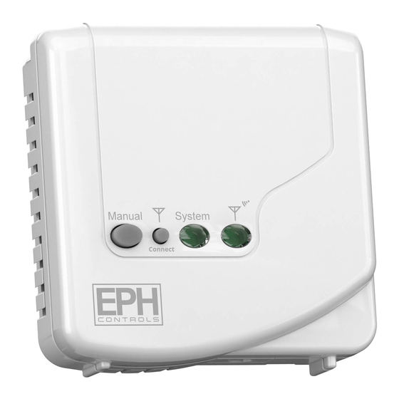
EPH Controls RF1A-OT Gebruiksaanwijzing
Blader online of download pdf Gebruiksaanwijzing voor {categorie_naam} EPH Controls RF1A-OT. EPH Controls RF1A-OT 2 pagina's. With rfrp-ot
Ook voor EPH Controls RF1A-OT: Gebruiksaanwijzing (2 pagina's)

RF1A-OT - Wireless Receiver
RF1A-OT - Wireless Receiver
with RFRP-HW-OT
with RFRP-HW-OT
Contents
2.
Mounting
3.
Installation
4.
Button / LED description
5.
Resetting the RF1A-OT receiver
6.
To connect the RFRP-HW-OT thermostat to an
RF1A-OT receiver
7.
To disconnect the RFRP-HW-OT thermostat from an
RF1A-OT receiver
Important: Keep this document
Prior to operation, it is neccessary to complete all
required settings described in this section.
1.
Power Supply: 200 - 240Vac
50-60Hz
Contact Rating: 250 Vac 10(3)A
Ambient Temp: 0~45°C
Automatic Action: Type 1.C.Q
Internal wiring diagram
for RF1A-OT
* If mains voltage output is required, terminals L & 2 must be electrically linked.
Important: Do not connect Mains Voltage to OpenTherm® terminals.
2. Mounting
The RF1A-OT receiver should be wall mounted in an area within 20
metres distance of the wireless thermostat.
It is important that the receiver is mounted more than 1 metre away from
The receiver should also be installed at least 1metre from any electronic
devices such as radio, TV, microwave or wireless network adaptor.
3. Installation
Slacken the fastening screw on the bottom of the receiver with a philips
screwdriver.
The receiver is hinged and can be opened 180 degrees. Mount the unit as
described in section 2. Wire the unit as described in section 1. Close the
receiver and tighten the fastening screw.
EPH Controls Ireland
[email protected] www.ephcontrols.com
Class II appliance
Pollution degree: Pollution degree2
Rated Impulse Voltage: Resistance to
voltage surge 2500V; as per EN 60730
IP Rating: IP20
3
2
1
L
N
O T
L
N
COM
ON
OFF
O T
MAINS SUPPLY
2. Surface mounting boxes
Page 1 of 2
Operating Instructions
Before commencing any work on the electrical
mains. None of the 230V connections must be live until the
installation has been completed and the housing is closed.
permitted to open the terminal box.
There are parts that carry mains voltage behind the cover. The
terminal box must not be left unsupervised when open.
(Prevent non specialists and especially children from gaining
access to it.)
Ensure that this wireless enabled receiver is installed 1 metre
from any metalic object, television, radio or wireless internet
transmitter.
4. Button / LED description
Connect button
Manual override
Wireless connect: Once voltage has been applied this button may be
pressed to initialise the pairing process with the wireless thermostat. Once
Manual override: This button will manually override the system.
LED description:
OT Connection Normal Operation
RF1A-OT On
OT Communication Error
RF1A-OT On
RF Communication Error
RF1A-OT On
Summary
RF Communication Error
OT Communication Error
Normal Operation RF1A On
EPH Controls UK
[email protected] www.ephcontrols.co.uk
CAUTION!
System ON
(Green LED)
Reset button
Wireless connect
indicator (Red LED)
Green LED
Red LED
ON
communicating via RF
OFF
communicating via RF
Green LED
Red LED
Constant Flash
OFF
Constant Flash
ON
Green LED
Red LED
ON
Constant Flash
OFF
Constant Flash
Green LED
Red LED
OFF or ON
Constant Flash
Constant Flash
OFF or ON
ON
OFF or Flashing
OFF
ON or Flashing
20221005_RF1A_OT_RFRP-HW-OT_Opins_PK
