AccuLine 40-6910 22x Servicehandleiding - Pagina 2
Blader online of download pdf Servicehandleiding voor {categorie_naam} AccuLine 40-6910 22x. AccuLine 40-6910 22x 9 pagina's. Builders level

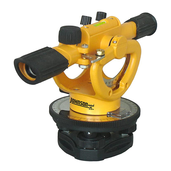
1. Overall Instrument Assembly
This optical level is a highly accurate instrument. Out side of a few customer
adjustments (outlined in the owners manual), all adjustments/service operations are
internal to the instrument and to be performed only by authorized service personnel.
Authorized personnel should adhere to the guidelines described within this service
manual for all repairs and/or service work. It should be note that procedures in
this manual should be referred to based on the specific situation.
1.1 Main Assembly (40-6910)
Item
JLT Part
1.
Remove rubber cover 3 (1), Rubber cover 1 (5), and Rubber cover 2
1
AP1990
Rubber Cover 1
(7) by gently pulling and twisting until parts come off.
2
AP1991
Rubber Cover 2
2.
Remove Horizontal Lock Knob (3) by continually turning counter
3
AP1992
Rubber Cover 3
clockwise until screw comes out.
3.
4
Remove
AP1993
Press Spring Screw
4.
xxx
5
AP1994
Horizontal Press Spring
5.
xxx
6
AP2026
Telescope Assembly
6.
Remove the Telescope Assembly (6) from the Base Assembly (8) by
7
AP1996
Horizontal Pres Spring Base
removing retaining screw (11), wave gasket (9), and gasket (10)
8
AP1997
Base Assembly
9
AP1998
Wave Ring
10
AP1999
Retainer
1)
Using a cross screwdriver to disassemble cross-slot
11
AP2000
M4x8 Cross Sunk Screw
plate screw M2×4(4#).
13
AP2027
Frame Assembly
2)
Counterturn the horizontal micro-motion knob on the
14
AP2028
Vertical Fine Adjustment Knob
15
AP1022
M3x6 Cross Plate Screw
16
AP2029
Press Cover
17
AP2030
Vertical Locking Knob
18
AP2031
Dampening Piece
19
AP2032
Press Spring
1.
Remove Rubber 1 (#1), rubber cover 2 (#2), and rubber cover 3 (#3) by hand.
2.
Remove vertical locking knob (#17) and vertical fine adjustment knob (#14) from frame assembly (#13) by turning counter
clockwise.
3.
Remove telescope assembly (#6) from Frame Assembly (#13) by removing 4 Retaining screws (#15), 2 Press covers (#16),
2 dampening pieces (#18), and Press Springs (#19).
4.
Remove Frame Assembly (#13) from Base Assembly (#8) by removing Retaining screw (#11), Wave ring (#9), Retainer
(#10), Press Spring Screw (#4), Horizontal Press Spring (#5), and Horizontal Press Spring base (#7).
Prepared By: Tim Wojo
Description
Revision: 1-050309
40-6910 Service Manual
Qty
1
1
1
1
1
1
1
1
1
1
1
1
1
4
2
1
2
2
Page 2 of 9
