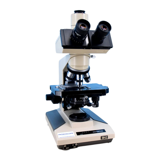
Olympus B2-BDS-2 Handleiding voor probleemoplossing en afstelling - Pagina 30
Blader online of download pdf Handleiding voor probleemoplossing en afstelling voor {categorie_naam} Olympus B2-BDS-2. Olympus B2-BDS-2 46 pagina's. For electrical base

C.
ADJUSTMENT (B2-BDS-2)
No.
C-l
1.
Measuring
Instruments To Be Used
RMS type
multimeter
(A multimeter
capable of measuring an RMS value)
*
An
ordinary
multimeter
can
not be used.
Lamp
house with a 12V/l00W halogen lamp
*
Use a
lamp house
with
small contact resistance and not used for
a long time.
2.
Locations of Adjusting
Trimmers
LED
one
RV2
RVl
UYPC65
3.
Adjustment Procedure
®
(j)
@
Set
the light intensity control lever to the "Min" position, and
turn on
the main switch.
Set the
light intensity control lever to the "Max" position.
Turn the
adjusting
trimmer RV2 fully clockwise.
Turn the
adjusting trimmer RVl fully counterclockwise.
Measure
the lamp output voltage with a multimeter (RMS type), and
turn the adjusting
trimmer RVl clockwise so that 11.8
±
0.
2V is obtained.
*
Measure the
output voltage at the brass part for
connecting
the lamp
house as illustrated
below.
type multimeter
Turn the adjusting
trimmer RV2 counterclockwise to set the
output
voltage
to 11.7 ± 0.2V.
Set the
light intensity
control
lever to the "Min"
position,
and
verify
that the output voltage is 3V or lower.
*
Defective
if the
voltage
is not lower than 3V.
Repair
or
replace
the PCB UYPC65.
Turn
off
the power,
and wait until the lamp goes out completely.
Set the
light intensity control lever to the "Min" position, turn
on
the
power
and verify that the lamp is lit.
Verify
that only the left-most LED is lit when the light intensity
control lever
is set to the "Min" position and all the LEDs are lit
when
the lever is set to the "Max" position.
