Axminster Trade 105784 Originele handleiding - Pagina 6
Blader online of download pdf Originele handleiding voor {categorie_naam} Axminster Trade 105784. Axminster Trade 105784 16 pagina's. Cyclone extractors
Ook voor Axminster Trade 105784: Originele handleiding (16 pagina's)

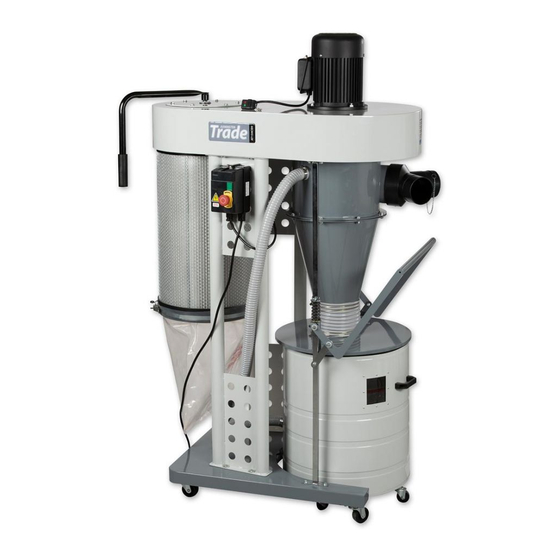
ASSEMBLY INSTRUCTIONS
These extractors come almost completely assembled with the exception
of the mobility castors, waste bin suction hose, switch and inlet adaptor.
Once you had dismantled the crate, remove the waste bin. Now place
some short lengths of 50 x 100mm timber upright on the floor and with
help manhandle the extractor onto the timbers.
Inside the waste bin there should be a pack containing the two sets of
castors, 4 with brake pedals, 4 smaller swivel castors.
The braked castors use 4 x M* bolts each, these fit under the base frame
at each corner. Fit one to each corner and tighten the bolts securely
(Figures 01 and 02).
Figure 01
Now fit the castors to the underside of the waste bin and tighten
securely (Figures 03 and 04).
Figure 03
Carefully remove the machine from the timbers onto it's castors.
Fit the vacuum hose to the outlet near the bottom of the waste bin.
Tighten the clip securely. (Figure 05)
Figure 05
Remove the remaining items from the
waste bin. The waste bin fits into a recess
in the base plate, so with the large handle
lowered, place the bin against the two
rubber stoppers (Figure 06), and raise the
handle (Figure 07).
Figure 02
Figure 04
Figure 06
Figure 07
Unpack the switch, there should be a small pack containing two small
machine screws with nuts, and the remote control fob.
The switch is mounted with the two machine screws here (Figure 08),
Figure 08
Remove the lid from the switch, (Figure 09)
Leave it loose (or get an assistant to hold it), taking care not to disturb
any wiring, fit one machine screw down the now open hole (Figure 10),
Figure 10
Fit the screw through the hole in the frame and secure using a nut on
the back (Figure 11).
Repeat for the lower side (Figure 12),
Figure 12
Refit the lid, carefully checking that no wires become pinched or
trapped (Figure 13).
The remote control fob has a sliding cover that protects the buttons,
slide back to expose the red and green stop and start buttons. When
using, please make sure that the main switch box "STOP" button has
been released, twist clockwise to make sure.
6
Figure 09
Figure 11
Figure 13
