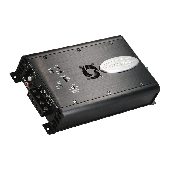
ARC Audio KS125.2 MINI Handleiding voor installatie-instructies - Pagina 11
Blader online of download pdf Handleiding voor installatie-instructies voor {categorie_naam} ARC Audio KS125.2 MINI. ARC Audio KS125.2 MINI 17 pagina's. Moto series

H. Next Plug in the Amplifiers 5 pin Hi Level
Speaker input plug (Provided with Amplifier) (See
Figrue 5H) and using the provided blue butt crimp
connectors attach the provided speaker wire to the
wires extending from the plug. Extend and route the
leads as necessary to reach the motorcycles factory
speaker wires from the radio near where the factory
speakers connect.
K. Now remove the factory speaker connection from
the factor speaker and using your wire cutters, cut
the factory connection plug from the factory speaker
wires. Now using a soldering iron of the provided
blue butt connectors, connect the wires comming from
the radio to the wires you just ran from the ampli-
fiers 5 wire hi level input plug then secure with
wire zip ties, (See Figure 5I)
Wire codes from amplifier hi-level plug -
White -
White w/black stripe-
Gray-
Gray w/black stripe
Wire colors from radio-
White w/orange stripe
Green w/white stripe
Gray w/red stripe
Green w/black stripe
L. Your last step in wiring your amplifier is to
connect the speakers to the amplifiers output
terminals(See Figure 5J. (Make sure at this point
the speakers are not connected to the factory
radio!!!) Using either the remainder of the speaker
wire provided with the kit or the pre terminated
wires provided with the speakers, insert and screw
down the wire tightly into the amplifiers output
terminals making sure to take note of left and right
channel assignment, then route the wires safely and
neatly toward the correct speaker on your motorcycle
and connect them to your speakers.
M. Now that everything is connected please proceed
to page 15 of this manual for detailed instructions
on how to adjust all of the settings on your KS125.2
Mini amplifier and on the factory radio.
Proceed to page 15 for crossover
and level setting instructions!!
Firugre 5H-
Figure 5I-
Figure 5J-
Left Positive
Left Negative
Right Positive
Right Negative
Left Positive
Left Negative
Right Positive
Right Negative
