ADDITIONAL JOB INFORMATION NEEDED:
1. MEASUREMENT RANGE: the range of the values that can be measured by the Controller (e.g. a
controller set to measure CO2 from 0ppm to 1100ppm).
2. ANALOG SIGNAL TYPE: vdc or mA.
3. MINIMUM SIGNAL VALUE of the analog signal: e.g. 0vdc or 4mA. This is the signal that the controller
puts out when it is measuring at the bottom of its measurement range.
4. MAXIMUM SIGNAL VALUE of the analog signal: e.g. 10vdc, 20mA. This is the signal that the controller
puts out when it is measuring at the top of its measurement range
5. SIGNAL RANGE: the difference between the maximum and minimum signal values from the controller.
In the case of a 0-10vdc controller the Signal Range is 10vdc. In the case of a 4-20mA Controller the
Signal Range is 16mA.
6. ACTION LEVEL SIGNAL: the value of the analog signal corresponding to the "Action Level".
7. MAXIMUM RESPONSE LEVEL SIGNAL: the value of the analog signal corresponding to the "Maximum
Response Level".
F9 APPLICATION EXAMPLE: CO2 CONTROLLER
The engineer wants the ERV to:
• Run at a minimum of 700 CFM, regardless of CO2 levels, in order to control the level of indoor air
pollutants generated by the furnishings.
• Start to increase airfl ow when CO2 levels rise above 600ppm.
• As CO2 levels continue to rise, the ERV should increase airfl ow, hitting a maximum of 1500 CFM at 1000
ppm CO2 level.
The CO2 controller is set up to deliver a linear 4-20mA signal over a measurement range of 0 to 1100ppm.
During the test and balance process, the ERV is found to deliver 700 CFM at 20Hz, and 1500CFM at 50Hz.
THEREFORE:
ACTION LEVEL = 600ppm
MAXIMUM RESPONSE LEVEL = 1000ppm
MAXIMUM SPEED = 50Hz
MINIMUM SPEED = 20Hz
ANALOG SIGNAL TYPE = mA.
MINIMUM SIGNAL VALUE = 4mA
MAXIMUM SIGNAL VALUE = 20mA
SIGNAL RANGE = 16mA
MEASUREMENT RANGE of the controller = 1100ppm
2
This does not mean the range of values that will be measured. For example, a CO2 controller might be set so that it can measure from 0ppm to 1100ppm. The Measurement Range is therefore
0-1100ppm. In the fi eld the controller might never read a value below 400ppm or above 1000ppm, but this is not the meaning of Measurement Range.
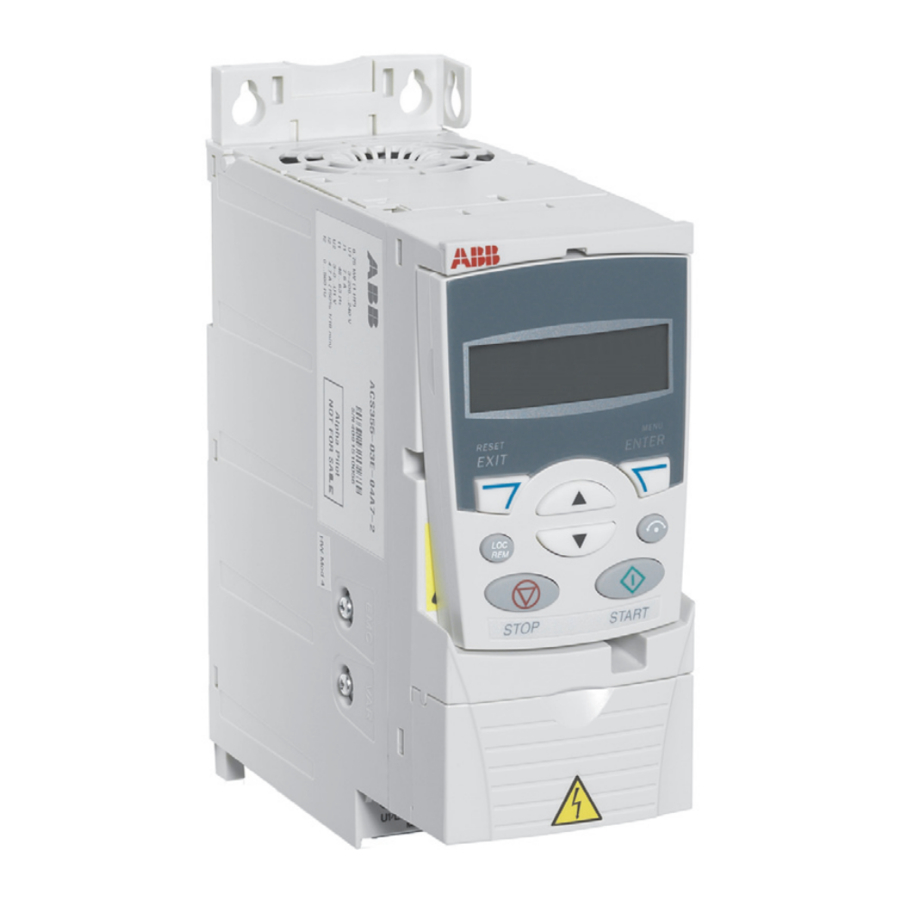
ABB VARIABLE FREQUENCY DRIVES
2
1.800.627.4499
OPERATION
SETTINGS
ABB VFD SUPPLEMENTAL MANUAL
RENEWAIRE.COM
15

