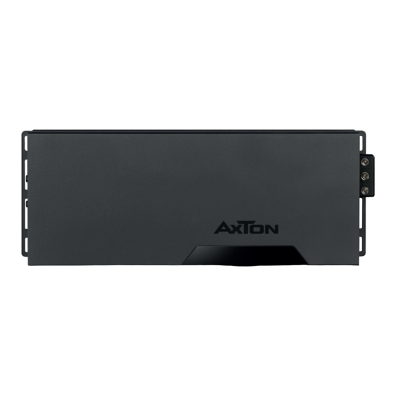
AXTON A401 Installatie- en bedieningshandleiding - Pagina 2
Blader online of download pdf Installatie- en bedieningshandleiding voor {categorie_naam} AXTON A401. AXTON A401 18 pagina's. 1-/2-/4-/6-channel power amplifiers

Thank you for purchasing this AXTON amplifier!
To maximize the performance of this amplifier and your complete car audio system installation,
we recommend you acquaint yourself thoroughly with all technical features and controlling
options of this AXTON amplifier. Please read this manual carefully, before attempting the
installation.
If, after reading this manual, you still have questions regarding functions or the installation of
the amplifier, we recommend that you consult your dealer.
SAFETY INSTRUCTIONS
Do not turn on any function which may distract you while driving your vehicle.
n
Functions requiring sustained attention must only be used when the vehicle is at a
complete standstill. Make sure to always stop your vehicle in a safe place before
operating these functions. There are risks of causing an accident.
Keep the volume at a low level to be able to hear exterior noises while driving
n
the vehicle. There are risks of causing an accident.
Do not open the amplifier or undertake any modification of the product. There
n
is a risk of accident, fire or electric shock.
Only use this amplifier with 12V mobile applications. Any use other than for this
n
product intended are may lead to fire, electric shock or injury.
Use correct amperage fuses. There are risks of fire or electrocution.
n
Do not obstruct radiators and/or vents. Internal overheating may occur and cause
n
a fire.
Ensure all connections are properly made. Check the section of cable and the
n
type of cable if it does not correspond with the use. There is a risk of fire, injury and/
or damage to the product.
Do not use screw nuts or fasteners part of the steering or braking systems for
n
ground connection. The fasteners and nuts used for the brake and steering systems
(or any other security system) as well as various tanks must never be used for
grounding. Use of these parts as ground may deactivate the vehicle's control system
and cause a fire or other technical problem.
Keep all small objects which could be swallowed, such as the fasteners and
n
screws, out of the reach of children. Swallowing such objects may cause serious
injuries. In the event of swallowing any of these objects, immediately seek medical
advice.
Before starting the installation, disconnect the negative terminal of the battery
n
to avoid any risk of injury, fire or damage to the equipment.
–
–
2
TECHNICAL SPECIFICATIONS
MONO AMPLIFIER A101
230 W x 1 @ 4 Ohm (< 1 % THD / 14.4 V)
380 W x 1 @ 2 Ohm (< 1 % THD / 14.4 V)
600 W x 1 @ 1 Ohm (< 1 % THD / 14.4 V)
Frequency response: 15 Hz – 250 Hz
Variable input sensitivity: 0.4 – 10 V
Signal to noise ratio: > 86 dB
Low pass filter: 50 – 250 Hz
Subsonic filter: 10 – 55 Hz
Dimensions LxWxH: 185 x 40 x 105 mm
2-CHANNEL AMPLIFIER A201
150 W x 2 @ 4 Ohms (< 1 % THD / 14.4 V)
260 W x 2 @ 2 Ohms (< 1 % THD / 14.4 V)
500 W x 1 @ 4 Ohms (< 1 % THD / 14.4 V)
Frequency response: 15 Hz – 35 kHz
Variable input sensitivity: 0.4 – 10 V
Signal to noise ratio: > 88 dB
High pass filter: 40 – 400 Hz
Low pass filter: 40 – 400 Hz
Dimensions LxWxH: 205 x 40 x 105 mm
4-CHANNEL AMPLIFIER A401
100 W x 4 @ 4 Ohm (< 1 % THD / 14.4 V)
170 W x 4 @ 2 Ohm (< 1 % THD / 14.4 V)
350 W x 2 @ 4 Ohm (< 1 % THD / 14.4 V)
Frequency response: 10 Hz – 35 kHz
Variable input sensitivity: 0.4 – 10 V
Signal to noise ratio: > 85 dB
High pass filter: 40 – 400 Hz
Low pass filter: 40 – 400 Hz
Dimensions LxWxH: 230 x 40 x 105 mm
6-CHANNEL AMPLIFIER A601
100 W x 6 @ 4 ohms (< 1 % THD / 14.4 V)
160 W x 6 @ 2 ohms (< 1 % THD / 14.4 V)
320 W x 3 @ 4 ohms (< 1 % THD / 14.4 V)
Frequency response: 10 Hz – 35 kHz
Variable input sensitivity: 0.4 – 10 V
Signal to noise ratio: > 85 dB
High pass filter: 40 – 400 Hz
Low pass filter: 40 – 400 Hz
Dimensions LxWxH: 282 x 40 x 105 mm
–
–
3
