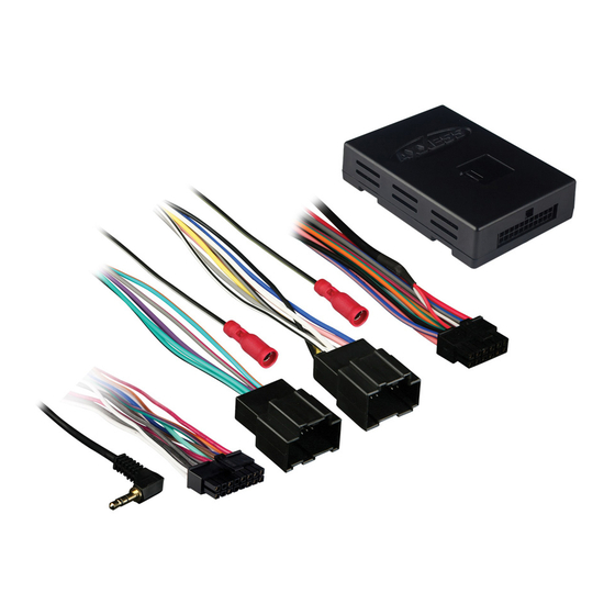
Axxess GMOS-LAN-01 Handleiding voor installatie-instructies - Pagina 3
Blader online of download pdf Handleiding voor installatie-instructies voor {categorie_naam} Axxess GMOS-LAN-01. Axxess GMOS-LAN-01 8 pagina's. Gm onstar lan data bus interface

TOOLS REQUIRED FOR INSTALLATION
• Cutting Tool • Tape • Crimping Tool • Connectors (ie: butt-connectors, bell caps, etc.)
INSTALLING THE INTERFACE
* Important: Before beginning any of the following, disconnect the negative battery terminal to prevent acci-
dental short circuit.
FOR INSTALLATION OF AFTERMARKET RADIO ONLY:
From the 14 pin harness:
1. Connect the red wire to the ignition/accessory wire of the aftermarket radio.
2. Connect the orange wire to the illumination wire of the aftermarket radio. If the aftermarket
radio has no illumination wire just tape off the orange wire.
3. Connect the Blue/white wire to the amp turn on wire of the aftermarket radio.
4. Connect the white wire to the left front positive speaker output of the aftermarket radio.
5. Connect the white/black wire to the left front negative speaker output of the aftermarket radio.
6. Connect the gray wire to the right front positive speaker output of the aftermarket radio.
7. Connect the gray/black wire to the right front negative speaker output of the aftermarket radio.
8. Connect the brown wire to the mute wire of the aftermarket radio. If the after market radio does not have
a Mute wire, tape up the brown wire.
The following wires on the 14 pin harness are for the aftermarket radios that have navigation built in:
1. Connect the green wire to the parking brake wire of the aftermarket navigation radio.
2. Connect the blue/pink wire to the VSS or speed sense wire of the aftermarket navigation radio.
3. Connect the green/purple wire to the reverse wire of the aftermarket navigation radio.
From the 12 pin harness:
1. Connect theYellow wire to the 12 volt constant/battery wire of the aftermarket radio.
2. Connect the Black wire to the ground wire of the aftermarket radio.
3. The Black/Yellow and Black/White wires will be discussed later in this manual.
From the 30 pin GM harness:
1. Connect the Green wire to the left rear positive speaker output of the aftermarket radio.
2. Connect the Green/Black wire to the left rear negative speaker output of the aftermarket radio.
3. Connect the Purple wire to the right rear positive speaker output of the after-market radio.
4. Connect the Purple/Black wire to the right rear negative output of the aftermarket radio.
(See wiring diagram 1 on page 3
GMOS-LAN-01
2
