CIRCUIT DESIGN CDP-RX-02AN Bedieningshandleiding - Pagina 7
Blader online of download pdf Bedieningshandleiding voor {categorie_naam} CIRCUIT DESIGN CDP-RX-02AN. CIRCUIT DESIGN CDP-RX-02AN 17 pagina's. Uhf fm-narrow band synthesized radio data module
OPERATION INSTRUCTIONS
Please read these instructions before you start using the CDP-02N.
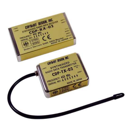
The CDP-02N is designed as a module which will be integrated into a user system. It is not a
ready-made product for private users. It can be regarded more like a special component for
part of an electronic system. The user needs basic knowledge about electronics. Special
knowledge about RF technology is helpful, but the most difficult parts are integrated into the
modules to enable easy operation. Some additional information is given here:
Supply voltage:
The transmitter and receiver module contain a voltage regulator to guarantee stable
performance in the given range of supply voltage.
The design was made for operation with a battery or regulated power source. If the battery
voltage drops below the minimum voltage given in the technical specifications, the transmitter
output power will drop and the RF oscillator will stop operation. No data can be transmitted in
this case. The receiver will continue to work down to a certain voltage but the performance
will deteriorate.
If the voltage connected to the Vcc (+) and Ground (-) terminal is above the maximum voltage
given in the technical specification the internal voltage regulator will be permanently
damaged. The result is an internal short-circuit or disconnection.
To enable a low minimum voltage no internal circuit is used to prevent damage by incorrect
polarity. If the transmitter is connected incorrectly, it will be permanently damaged. If a higher
supply voltage is available then a simple diode can be inserted in the connection line to the
Vcc terminal to prevent damage by incorrect polarity. The diode must be rated for the
maximum supply current detailed in the technical specifications.
Modules which have been connected to improper voltage sources should be returned to the
dealer for inspection.
Data input:
The data input terminal is connected to a digital transistor compatible input. Data
sources of high impedance can be used is acceptable.
The voltage of the data signal should be between 0V (Ground level) and Vcc. Because of the
internal voltage regulator, it is recommended that the data high level be limited to 5 Volts.
The data can be an analog or digital signal. Analog signals will be converted to a digital 1 or 0
inside the transmitter.
It is not necessary to synchronize the data signal of the transmitter, but the data signal should
be fed to the transmitter 80ms after the transmitter power on.
CDP-02N UHF Synthesized Radio Data Module Operation Guide
CIRCUIT DESIGN, INC.
6