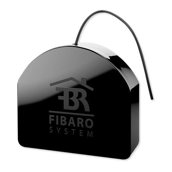
FIBARO Dimmer 2 Snelstarthandleiding - Pagina 5
Blader online of download pdf Snelstarthandleiding voor {categorie_naam} FIBARO Dimmer 2. FIBARO Dimmer 2 14 pagina's.

2021. 04. 16.
FIBARO Dimmer 2 is equipped with a B-button, which allows to use the MENU mode and additionally perform the following actions:
1x click:
• alarm mode cancellation (flashing alarm)
• exit the error mode
• select the desired MENU option (if MENU mode is active)
3x click:
• send the Node Info Z-Wave command frame (adding/removing)
Holding:
• enter the MENU mode (confirmed by the LED indicator)
MENU mode & visual indications:
FIBARO Dimmer 2 has a MENU with each position indicated by the specified LED indicator colour. In order to enter the menu press the B-button and hold for at
least 2 seconds. While the B-button is still pressed, LED indicator colour will change in the following sequence: BLUE - initiate the load calibration procedure (see
„Calibration" on page 15)
RED - load calibration procedure with FIBARO Bypass 2 (see „Calibration" on page 15)
WHITE - activate turning the load on/off using the B-button
GREEN - reset the energy consumption data memory (see „Power and energy consumption measurement" on page 16)
VIOLET - initiate the Z-Wave network range test (see „Z-Wave range test" on page 18)
YELLOW - reset the FIBARO Dimmer 2 to factory defaults Release the B-button to choose the desired function and confirm your choice with the B-button click.
Communication to a Sleeping device (Wakeup)
This device is battery operated and turned into deep sleep state most of the time to save battery life time. Communication with the device is limited. In order to
communicate with the device, a static controller C is needed in the network. This controller will maintain a mailbox for the battery operated devices and store
commands that can not be received during deep sleep state. Without such a controller, communication may become impossible and/or the battery life time is
significantly decreased.
This device will wakeup regularly and announce the wakeup state by sending out a so called Wakeup Notification. The controller can then empty the mailbox.
Therefore, the device needs to be configured with the desired wakeup interval and the node ID of the controller. If the device was included by a static controller this
controller will usually perform all necessary configurations. The wakeup interval is a tradeoff between maximal battery life time and the desired responses of the
device. To wakeup the device please perform the following action: The Fibaro Dimmer 2 is powered with mains voltage so it is always awake.
Quick trouble shooting
Here are a few hints for network installation if things dont work as expected.
1. Make sure a device is in factory reset state before including. In doubt exclude before include.
2. If inclusion still fails, check if both devices use the same frequency.
3. Remove all dead devices from associations. Otherwise you will see severe delays.
4. Never use sleeping battery devices without a central controller.
5. Dont poll FLIRS devices.
6. Make sure to have enough mains powered device to benefit from the meshing
Firmware-Update over the Air
This device is capable of receiving a new firmware 'over the air'. The update function needs to be supported by the central controller. Once the controller starts the
update process, perform the following action to confirm the firmware update: Dimmer 2 features remote software update (initiated by the main controller). Update
status is signalled by the LED indicator with cyan colour:
• slow blinking - transferring data via Z-Wave and saving to the flash memory
• fast blinking - copying data from the external memory to the memory of the microcontroller
Association - one device controls an other device
Z-Wave devices control other Z-Wave devices. The relationship between one device controlling another device is called association. In order to control a different
device, the controlling device needs to maintain a list of devices that will receive controlling commands. These lists are called association groups and they are
always related to certain events (e.g. button pressed, sensor triggers, ...). In case the event happens all devices stored in the respective association group will
receive the same wireless command wireless command, typically a 'Basic Set' Command.
Association Groups:
Group Number
1
2
3
4
5
Configuration Parameters
Z-Wave products are supposed to work out of the box after inclusion, however certain configuration can adapt the function better to user needs or unlock further
enhanced features.
https://manual.zwave.eu/backend/make.php?lang=en&sku=FIBEFGD-212
https://manual.zwave.eu/backend/make.php?lang=en&sku=FIBEFGD-212
Maximum
Description
Nodes
1
Z-Wave Plus Lifeline. Type of frame sent by the device when the association group is activated:
SWITCH_MULTILEVEL_REPORT; DEVICE_RESET_LOCALLY_NOTIFICATION;
SCENE_ACTIVATION_SET; METER_REPORT; SENSOR_MULTILEVEL_REPORT;
NOTIFICATION REPORT.
8
Association Group On/Off (S1) is assigned to key no. 1. Type of frame sent by the device when the
association group is activated: BASIC_SET.
8
Association Group Dimmer (S1) is assigned to key no. 1. Type of frame sent by the device when the
association group is activated: SWITCH_MULTILEVEL_SET.
8
Association Group On/Off (S2) is assigned to key no. 2. Type of frame sent by the device when the
association group is activated: BASIC_SET.
8
Association Group Dimmer (S2) is assigned to key no. 2. Type of frame sent by the device when the
association group is activated:SWITCH_MULTILEVEL_SET.
5/14
