Siemens Simatic S7-300 Aan de slag - Pagina 8

Blader online of download pdf Aan de slag voor {categorie_naam} Siemens Simatic S7-300. Siemens Simatic S7-300 8 pagina's. Automation systems, controlling a physical axis
Ook voor Siemens Simatic S7-300: Gebruikershandleiding (34 pagina's), Handmatig (21 pagina's), Gebruiksaanwijzing (4 pagina's), Gebruiksaanwijzing (5 pagina's), Handmatig (35 pagina's), Aan de slag (16 pagina's), Toepassing Beschrijving (24 pagina's), Handmatig (18 pagina's), Handmatig (32 pagina's), Installatie- en hardwarehandleiding (20 pagina's), Aan de slag (32 pagina's)
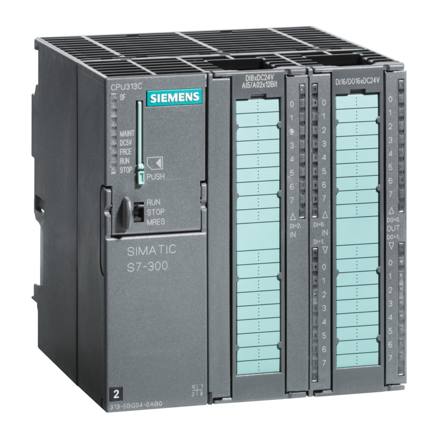
Siemens Simatic S7-300 Aan de slag

Step 6: Test Run

Stage
1
Navigate via SIMATIC 300 Station and CPU 314(1) to
S7 Program. In SIMATIC Manager, click Blocks in the
right-hand part of the window.
2
From the PLC menu, choose the Download command
to transfer the program and the hardware configuration
to the CPU.
Click Yes in all the dialog boxes that appear.
3
Switch the CPU mode selector to RUN .
4
Operate the two switches alternately.
5
Operate the two switches simultaneously.
Diagnosis/Debugging
Incorrect operation, incorrect wiring or incorrect hardware configuration can result in faults
that the CPU indicates after a memory reset with the group error LED SF .
You can find out how to evaluate these errors and messages in the manuals: Hardware and
Installation ; Section 8.3.2 and Programming with STEP 7 V5.0 ; Chapter 21.
Manuals for Further Information
We recommend that you also read Getting Started First Steps with STEP 7 V5.0 .
You can download all the manuals free of charge from the Siemens home page (Products &
Solutions – Industrial Services – Support – SIMATIC – Customer Support).
Siemens AG
Bereich Automatisierungs- und Antriebstechnik
Geschäftsgebiet Industrie-Automatisierungssysteme
Postfach 4848, D-90327 Nürnberg
S7-300 Programmable Controller, Getting Started, First Steps for Installation and Commissioning
Siemens Aktiengesellschaft
8
Procedure
Subject to change without prior notice
A5E00069340
Printed in the Federal Republic of Germany
Blocks is highlighted.
The program and configuration are downloaded
from the programming device to the CPU.
The STOP LED goes out. The RUN LED starts
flashing and then comes on continuously.
The LEDs of the inputs E0.1 and E0.2 light up
alternately.
The LED of output A4.0 does not light up.
The LEDs of inputs E0.1 and E0.2 light up toge-
ther.
The LED of output A4.0 comes on. This would
switch on a connected actuator or indicator.
Siemens AG 2000
Result
A5E00069340 01 // 04/2000