Siemens SIWAREX R Gebruiksaanwijzing - Pagina 22
Blader online of download pdf Gebruiksaanwijzing voor {categorie_naam} Siemens SIWAREX R. Siemens SIWAREX R 38 pagina's. Mounting units for sb series
Ook voor Siemens SIWAREX R: Gebruiksaanwijzing (34 pagina's)

3
Combination Mounting Unit
3.1
Technical Description
3.1.1 Application Range
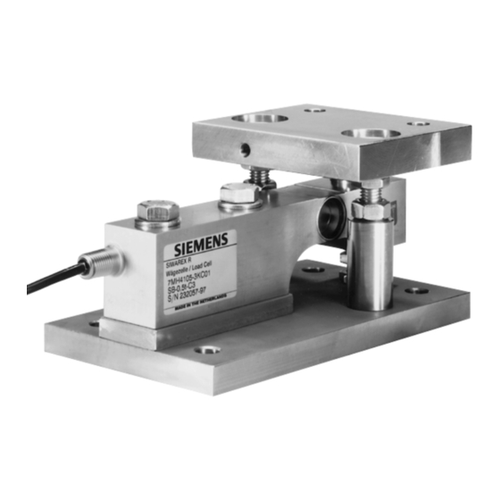
Combination mounting units are for direct force transmission to the load cells.
These are self-centering on the load platform.
The combination mounting units have the following features:
•
Integrated oscillation limitation.
•
Integrated lift-off protection.
•
Integrated overload protection
•
Can be used as dummy for light assembly work.
•
Slow, controlled lowering of the top plate.
•
Can be used as transport locking device by affixing the top plate to protect the
load cells.
3.1.2 Construction
The combination mounting unit consists of the base plate and top plate and two
countersunk bolts as an oscillation limitation and lift-off protection. It forms a mulit-
functional bearing unit together with the load cell.
The base plate (1) is bolted to the foundation with four bolts. The load cell (3) is fastened
to the base plate (1) with two hexagon bolts (5) and a spacer bar (2). An oscillation
housing (13) is inserted in the head of the load cell (3). The pendulum bolt (16)
positioned in it. The pendulum bolt is supported by two force guiding pieces (14) and
(17). The two force guiding pieces (14) and (17) are stuck in the oscillation housing (13)
and the top plate (18). The top plate (18) is supported on the pendulum bolt (16). The top
plate (18) is bolted to the loading platform. The loading platform is centered with the
pendulum bolt (16). Transverse movement of the load platform causes a restoring force
that puts the load platform back in the rest position.
The countersunk bolts (9) limit the possible movement of the top plate (18). Their second
function is to prevent the top plate from being lifted.
A flat seal (15) between the oscillation housing (13) and the top plate (18) protects the
force transmission mechanism from contamination.
The base plate is equipped with an adjustable overload protection (11). This limits the
measurement path of the load cell (3) and protects the equipment from any damages that
might be caused by accidental overloading.
(Numbering see Fig. 3-1)
Document No.: A5E00353789B
Page 22
