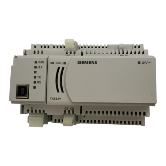
Siemens TXB1.P1-4 Installatie-instructies - Pagina 3
Blader online of download pdf Installatie-instructies voor {categorie_naam} Siemens TXB1.P1-4. Siemens TXB1.P1-4 4 pagina's. Tx-i/o bus interface module

Basic Steps for Connecting Devices to the
DIN Rail
The island bus establishes its own connection when
TX-I/O devices are plugged into one another on a DIN
rail.
1.
Slide out the mounting tabs.
2.
Align the channel on the back of the device with
the DIN rail.
3.
Using a flat blade screwdriver, push in each
mounting tab until it clips onto the DIN rail.
4.
Align an I/O module with the Power Supply or Bus
Connection Module and slide the I/O module
down over the TX-I/O island bus connector.
5.
Push in each mounting tab until it clips onto the
DIN rail.
Connecting Devices to the TX-I/O Island Bus.
Siemens Industry, Inc.
Completing the Installation
CAUTION:
For RS-485 ALN or FLN, terminate only one
end of the shield wire on the enclosure earth
ground.
For a 3-wire system,
to reference wire. Protective ground terminal
may be connected to earth ground.
For a 2-wire system,
connected. Protective ground terminal must
be connected to earth ground.
NOTE: Do not connect the power or network
communication cable until instructed to do so
during start-up.
1.
Terminate power wiring to the 24 Vac removable
plug.
2.
If necessary, terminate wires to the
communications terminals (CS and CD).
The installation is now complete.
Document No. 553-140
Installation Instructions
November 4, 2019
terminal is connected
terminal is not
Page 3 of 4
