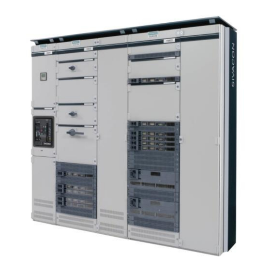
Siemens SIVACON S 8PQ Series Gebruiksaanwijzing - Pagina 27
Blader online of download pdf Gebruiksaanwijzing voor {categorie_naam} Siemens SIVACON S 8PQ Series. Siemens SIVACON S 8PQ Series 40 pagina's. Design-verified low-voltage switchboard
Ook voor Siemens SIVACON S 8PQ Series: Gebruiksaanwijzing (11 pagina's)

- 1. Table of Contents
- 2. Sivacon Bauartgeprüfte Niederspannungsschaltanlage S8 - Felder mit Abzweigen in Einschubtechnik Design-Verified Low-Voltage Switchboard S8- Cubicles with Feeders in Withdrawable Design Betriebsanleitung / Operating Instructions Bestell-Nr. / Order No.: 8P
- 3. Description of the MCC Cubicle
- 4. Electrical Connections
3.2.5 Handhabung Normaleinschub
Herausnehmen des Einschubes aus dem Fach
Hauptschalter ausschalten
Trennkontakte in Trennstellung bringen (siehe Abschnitt 3.2.2)
Fachtür öffnen
Die Hebel links und rechts unten am Einschub (siehe Bild
unten) bis zum Anschlag anheben. Einschub dabei nach vorn
aus dem Fach ziehen so dass dieser zum Entnehmen von un-
ten umgriffen werden kann. Einschub aus dem Fach entneh-
men. Für Einschübe mit einem Gewicht größer 20 kg empfiehlt
es sich, diese auf die Plattform eines geeigneten Hubwagens
zu ziehen. Werden diese von Hand entnommen, sind sie weit
genug herauszuziehen, links vorn zu untergreifen und zu stüt-
zen. Nach leichtem Neigen nach unten kann der Handgriff
rechts am Gerätetragblech gegriffen werden
Beim Lagern und Bewegen der Einschübe außerhalb des
Feldes ist darauf zu achten, dass die Haupt- und Steuerstrom-
kreiskontakte nicht mechanisch belastet, bzw. deformiert wer-
den.
Warnung
Das Heben von schweren Einschüben > 20 kg kann
zu Körperschäden führen. Unsicheres Hantieren mit
schweren Lasten führt leicht zur Sachbeschädi-
gung.
Einsetzen des Einschubes in das Fach
Öffnen der Fachtür
Prüfen ob der Einschub sich in der Trennstellung und der
Hauptschalter sich in der Stellung 0 befindet.
Einschübe bis 200mm Höhe links und rechts unterhalb mittig
des Gehäuses und größere Einschübe links unterhalb des Ge-
häuses und rechts oben an der Griffmulde anfassen.
Für Einschübe mit einem Gewicht größer 20 kg empfiehlt es
sich, diese von der Plattform eines geeigneten Hubwagens aus
in das Fach zu schieben.
Den Einschub mit der hinteren unteren Fläche auf dem Trag-
blech im Fach absetzen und ohne viel Schwung bis zum An-
schlag in das Fach einschieben.
Die Hebel links und rechts müssen im Fachboden nach unten
einklinken.
Fachtür schließen.
Öffnen der Instrumententafel
Die Instrumententafel links erfassen und nach links oben aufziehen.
Die Instrumententafel lässt sich dann aufschwenken.
8PQ9800-3AA48
3.2.5 Handling standard withdrawable units
Take-out of the withdrawable unit from the compartment
Switch off the main switch
Bring the isolating contacts into the disconnected position (see
section 3.2.2)
Open the compartment door
Lift the lever on the left and the right below on the withdrawable
unit until up to the stop (see figure below). Pull the withdrawable
unit forward from the compartment so that it can be gripped from
below. Take out the withdrawable unit from the compartment.
For withdrawable units with a weight larger than 20 kg, it is rec-
ommended to pull these onto a platform of a suitable lifting cart.
If the withdrawable unit is taken out by hand, then pull it out far
enough, grip from below and support on the front left. After a
slight incline downwards, the handle on the right side of the de-
vice mounting plate can be gripped.
Avoid any mechanical stress and deformation of main and con-
trol voltage contacts when handling the withdrawable unit out-
side the compartment.
Warning
The lifting of heavy withdrawable units > 20 kg can
lead to physical injuries. Unsafe handling with heavy
weights can easily lead to damage to property.
Inserting the withdrawable unit into the compartment
Open the compartment door
Check if the withdrawable unit is in the disconnected position
and the main switch is in the "0" position
Grip the withdrawable units of up to 200mm height below left
and right in the center of the housing and larger withdrawable
units left below the housing and top right at the recessed grip.
For withdrawable units with a weight larger than 20 kg, it is
recommended to push these from a surface of a suitable lifting
cart into the compartment.
Move the withdrawable unit with rear lower surface on the
supporting plate in the compartment and push it gently into the
compartment up to the stop.
The left and right levers must latch below to the compartment
bottom.
Close the compartment door.
Open the instrument panel
Grip the instrument panel on the left, pull it up to the top left. Then the
instrument panel can swing-open.
25
