ActronAir LC7-2W Handleiding voor installatie-instructies - Pagina 5
Blader online of download pdf Handleiding voor installatie-instructies voor {categorie_naam} ActronAir LC7-2W. ActronAir LC7-2W 8 pagina's. Wall control

Installation Guide
05. Controller Assignment
NOTE
For installations where an LC7-2 is being installed with a Neo Wall Control, C-1 will always need to be assigned to the Neo Wall
Control.
Upon initial start up of the system, all connected LC7-2 controls (up to 3) will display C-0. After 3 seconds, an auto-
assignment process will take place with the auto-assigned control ID displayed on the screen C-1, C-2 and C-3. The user
can change the control assignment between C-1 and C-3 with the
correctly, a C-1 control must be present, with each control requiring a unique control assignment. The displayed text will
remain on the control until user acknowledges the assignment by pressing the PROG button to enter the Home Screen.
Upon subsequent power cycles, all controls will show their control ID for 3 seconds before proceeding to the home
screen.
Manual Control Assignment
1.
Press and hold the REPEAT and TIMER buttons for 3 seconds then release to enter Service Menu.
2. Press the PROG button to enter Service Menu 01.
3. Press the
4. Press the PROG button to accept the selection.
5. Press the EXIT button once to return to Main Screen.
NOTE
In the case of disconnecting the C-1 control from the system, the other LC7-2 controls will show an error code (E56 - No main
wall control detected). To troubleshoot this error code:
• Troubleshoot C-1 LC7-2 control - check the wiring and connection of the control. If E56 is still being displayed on C-2 and
C-3, connect a replacement LC7-2 control. During its first power on cycle, it will auto assign itself to the vacant address.
06. Sensor Enable/Calibration
Press and hold the REPEAT and TIMER buttons for 3 seconds then release to enter Service Menu.
1.
2. Press the
button to scroll through to Service Menu 02.
3. Press the PROG button to enter Service Menu 02.
NOTE
The display will toggle between sensor name (CS1 - Wall Control Sensor 1) and actual temperature reading.
By default, all connected sensors are enabled, displayed ON, and have a calibration factor of 0.
CS1/CS2/CS3 represent wall control sensors and rS1/rS2 represents remote sensor.
4. Press the
5. Press the PROG button to enter Wall Control Sensor settings.
6. Press the
NOTE
Offset range is ±9.9, with 0.1 increments per
The
button may be pressed to enable/disable sensor.
7.
Press the PROG button to accept changes.
8. Repeat steps 4-7 to enable/disable and calibrate all applicable sensors.
9. Press the EXIT button twice to return to Main Screen.
or
buttons to select the appropriate control assignment.
buttons to select the appropriate sensor to calibrate or turn ON or OFF.
or
or
buttons to change the temperature offset of Wall Control Sensor.
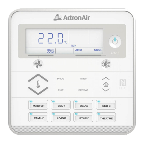
LC7-2 Control Interface Insert
Document: 9590-3024 Ver. 2 200702
LC7-2 Control Interface
or
or
buttons press.
buttons. For the system to function
05
