ACTUS 720 Series Basisinstellingen - Pagina 5
Blader online of download pdf Basisinstellingen voor {categorie_naam} ACTUS 720 Series. ACTUS 720 Series 7 pagina's.

Actuator Trouble Shooting
3.
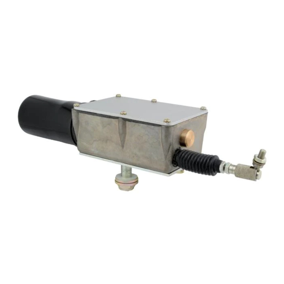
Remove the screws holding cover and gasket to actuator housing.
4.
Refer to drawing 999-0172 to check wiring
5.
Verify the BLUE wire (terminal block position #3) to negative ground
potential.
6.
Attach the RED wire (terminal block position #4) to negative ground.
7.
Attach the BLACK wire (terminal block position #5) to 12 volts. This
should cause the actuator to extend until contacting the limit switch.
8.
Now reverse the ground and 12 volts on the RED and BLACK wires. This
should cause the actuator to retract until contacting the limit switch. If
actuator operates as described, proceed with the following
potentiometer (pot) check, (where applicable). If the actuator DOES
NOT operate, continue with step #12 under Motor Check.
9.
If the actuator has a 2000 ohm linear pot attached to the P.C. board,
this pot provides a position feedback signal. If the pot is defective, the
actuator may run to either the fully retracted or extended position limit
switch then stop. It is rare that the pot will fail but it can be easily
checked with an ohmmeter.
10. Place the probes of the ohmmeter across the ORANGE and BROWN
wires. A reading of approximately 2000 ohms should be read.
11. Place the probes of the ohmmeter across the ORANGE and YELLOW
wires. Run the actuator back and forth as described earlier. As the
actuator moves from one end to the other, the pot value should move
between zero and 2000 ohms. If the actuator operates as described,
proceed with step #12. If the pot does not operate properly, the P.C.
board assembly can be replaced by ordering Actus part number 024-
0577.
Motor Check
12. Disconnect the RED and BLACK wires from the terminal block positions
#1 and #2 INSIDE the actuator. The motor can now be run directly by
applying 12 volts and ground to those wires.
CAUTION
In this configuration, the actuator limit switches are by-passed.
Be sure that the actuator is always connected to run toward the
furthest limit and power is applied only momentarily.
