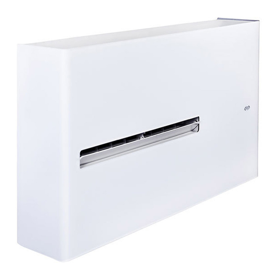
Argo DD DCI Handleiding voor installatie-instructies - Pagina 9
Blader online of download pdf Handleiding voor installatie-instructies voor {categorie_naam} Argo DD DCI. Argo DD DCI 16 pagina's. Air conditioner without outdoor unit

WARNING! The supplied plastic sheet can be used for wall
thickness up to 50 cm; in special cases (i.e. installations
in a garret) it can be necessary to utilise longer tubes.
The maximum allowable length is 2 m. You can go to any
building material retailer, buy the plastic tube of the same
diameter (ø160 mm), of the proper length and cover it
outside with insulating material (thickness: about 3-4 cm).
- Fix the hanging bracket to the wall in the position
indicated on the full scale diagram.
The quantity and the type of rawl plugs depends on the
consistence of the wall; do not let any space between
the panel and the wall.
- Hang up the unit at the bracket by simultaneously
inserting the condensate drainage pipe into the wall hole.
- Predispose a condensate drainage toward the outside
making a hole Ø 35 mm as indicated on the full scale
diagram. Assure always a positive slope of at least
1cm/m.
3.2 - ELECTRICAL CONNECTION
The air conditioner is equipped with a power cable with
plug (the electrical connection of the unit is Y type with
cable prepared in a special way; any replacement must
only be carried out by the authorized Service Center).
CAUTION
Before connecting the air conditioner, be sure that:
• The voltage of the mains power supply is the same as
the voltage shown on the nameplate.
• The power supply line has a ground connection and
it is correctly sized for maximum electrical input of
the air conditioner (minimum cable cross-section:
1,5mm
2
).
• The air conditioner is powered only through a socket
compatible with the plug supplied.
Main switch for disconnection from the supply line must
have a contact separation in all poles that provides
full disconnection under category III overvoltage
conditions.
Connect the unit inserting the plug in the power socket.
ELECTRICAL CONNECTION THROUGH A CABLE BUILT
INTO THE WALL
It is possible to proceed with the electrical connection
through a cable built into the wall as indicated in the full
scale diagram (recommended connection for installation
of the unit in the upper part of the wall).
• Disconnect the main switch before making the elec-
trical connection.
• Disconnect the power cable with plug from the ter-
minal block.
• Connect a similar cable, pass it through the appro-
priate hole on the full scale diagram (cut the rubber
grommet) and connect it to the cable built into the
wall.
Plastic tubes ø 160mm
Insulation
9
EN
