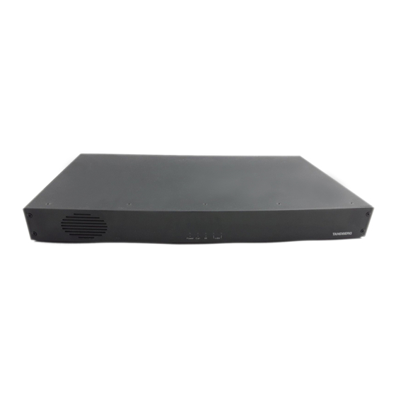
Cisco TelePresence System Codec 6000 MXP De fysieke interface handleiding - Pagina 22
Blader online of download pdf De fysieke interface handleiding voor {categorie_naam} Cisco TelePresence System Codec 6000 MXP. Cisco TelePresence System Codec 6000 MXP 28 pagina's.

MXP Series Codecs
Contents
Camera Socket
TIP!
Wherever applicable, the use of Category
5 cabling or better is strongly recommended!
For HD camera applications, however,
Category 7.5 is required.
S-video Mini-DIN pin-out
Split cable for
External view of socket
non-Cisco
cameras
4
3
2
1
Pin 1: Ground (Luminance)
Pin 2: Ground (Chrominance)
Camera side
Pin 3: Luminance (Y)
Pin 4: Chrominance (C)
9-pin D-sub pin-out
External view of socket
1
5
SIGNAL
NAME
+12V DC
GND
9
6
+12V DC
TXD
RXD
RJ-45 Connector
GND
pin-out
GND
+12V DC
1
8
Y-GND
TOP
C_GND
Y
C
FRONT
NC
1
8
D14790.01 MXP Series Codec Physical Interface Guide, May 2011.
© 2011 Cisco Systems, Inc. All rights reserved.
Introduction
Codec side
TANDBERG 3000 WAVE II
Camera cable pin-out
RJ-45
S-VIDEO
DSUB
8
—
4
7
—
5
3
—
4
4
—
3
5
—
2
6
—
5
2
—
5
1
—
4
—
1
8
—
2
1
—
3
9
—
4
6
—
—
7
Codec 6000 MXP
Camera Connect the camera here. Use
a Cisco 3000 WAVE II Camera cable or
similar.
To connect a non-Cisco camera use
the split cable supplied. This cable
has a female D-SUB and an S-video
connector in one end and a male
D-SUB connector in the other end.
TANDBERG HD 3000
Camera cable pin-out
SIGNAL
RJ-45
DSUB
NAME
+12V DC
1
Twisted pair
GND
2
Rx
3
Twisted pair
TX
6
LVDS+
4
Twisted pair
LVDS–
5
GND
7
Twisted pair
+12V DC
8
Cable is Category 7.5/ Class F AWG24.
CAUTION!
Extreme care should be taken if
you choose to make your own version of this
cable!
22
Physical interface guide
Codec 3000 MXP
Codec 3000 MXP
Non-TANDBERG
Camera cable pin-out
SIGNAL
DSUB
S-VIDEO
NAME
Camera
4
+12V DC
1
—
1
GND
2
—
2
+12V DC
3
—
3
TXD
4
—
6
RXD
5
—
9
GND
6
—
5
GND
7
—
4
+12V DC
8
—
Y-GND
—
1
C_GND
—
2
Y
—
3
C
—
4
NC
—
—
Contact us
DSUB
Codec
4
5
4
3
2
5
5
4
8
1
9
6
7
www.cisco.com
