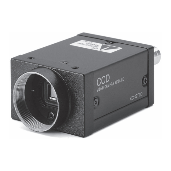
Sony XCST70 Handmatig - Pagina 2
Blader online of download pdf Handmatig voor {categorie_naam} Sony XCST70. Sony XCST70 4 pagina's. Black-and-white video camera module
Ook voor Sony XCST70: Producthandleiding (2 pagina's), Brochure (2 pagina's), Gebruikershandleiding (31 pagina's)

•
XC-ST50/XC-ST51/XC-ST30
(Typical Values)
Relative sensitivity
1.0
0.8
0.6
0.4
0.2
0
400
500
600
Wavelength (nm)
(Lens characteristics and light source characteristics excluded.)
Specifi cations
XC-ST70
Image device
2/3-type IT CCD
Signal system
Effective picture elements (H) × (V)
Effective lines (H) × (V)
Cell size (H) × (V)
11.6 μ m × 13.5 μ m
Horizontal frequency
Vertical frequency
Lens mount
Sync system
External Sync system input/output
*1
External Sync frequency
Jitter
Scanning system
Video output
Horizontal resolution
Sensitivity
Minimum illumination
S/N ratio
Gain
Gamma
Normal shutter
External trigger shutter
Power requirements
Power consumption
Dimensions
Mass
Operating temperature/humidity
Storage temperature/humidity
Performance guarantee temperature
Vibration resistance
Shock resistance
MTBF
Regulatory compliance
Supplied accessories
The values for mass and dimension are approximate.
*1
Automatic switching in response to the presence of an input signal when the switch on the rear panel is set to EXT.
700
800
900
1000
XC-ST50
XC-ST51
1/2-type IT CCD
EIA
768 × 494
752 × 485
8.4 μ m × 9.8 μ m
15.734 kHz
59.94 Hz
570 TV lines
400 lx, F8
400 lx, F11
(γ= ON, 0 dB)
(γ= ON, 0 dB)
0.3 lx
0.2 lx
(F1.4, AGC ON)
(F1.4, AGC ON)
60 dB
1/100 sec to 1/10,000 sec
1/4 sec to 1/10,000 sec
2.1 W
2.0 W
44 (W) × 29 (H) × 57.5 (D) mm (not including projecting parts)
105 g
110 g
10 G (20 Hz to 200 Hz 20 minutes for each direction–x, y, z)
UL6500, FCC/ICES-003 : Class B, CE : EN61326, AS/NZ : EN61326
Location and Function of Parts and Controls
1 Lens mount (C-mount)
Attach any C-mount lens or other optical equipment.
Note
The lens must not project more than 10 mm from the lens mount.
2 Reference holes (at the top)
These precision screw holes are for locking the camera module.
Locking the camera module using these holes secures the optical
axis alignment.
3 Reference screw holes/Tripod screw holes (at the bottom)
These precision screw holes are for locking the camera module.
Locking the camera module using these holes secures the optical
axis alignment.
You can install the camera on a tripod. To install on a tripod,
you will need to install the VCT-ST70I tripod adaptor using the
reference holes on the bottom of the camera.
XC-ST30
XC-ST70CE XC-ST50CE XC-ST51CE XC-ST30CE
1/3-type IT CCD 2/3-type IT CCD
6.35 μ m × 7.4 μ m 11.6 μ m × 11.2 μ m
C mount
Internal/External
HD/VD (HD/VD level: 2 V to 5 Vp-p)
±1% (in horizontal sync frequency), VS
less than ± 20 nsec (external horizontal frequency)
2:1 Interlaced
1.0 Vp-p, negative, 75 Ω unbalanced
400 lx, F5.6
400 lx, F8
(γ= ON, 0 dB)
(γ= ON, 0 dB)
0.3 lx
0.3 lx
(F1.4, AGC ON)
(F1.4, AGC ON)
56 dB
AGC/Fixed/Manual (adjustable on the rear panel)
ON/OFF (adjustable on the rear panel)
DC 12 V (10.5 V to 15 V)
1.9 W
2.1 W
105 g
−5˚C to +45˚C / 20% to 80% (no condensation)
−30˚C to +60˚C / 20% to 95% (no condensation)
0˚C to 40˚C
70 G
70,600 hours (Approx. 8.1 years)
Lens mount cap (1), Operating instructions (1)
XC-ST70/ST70CE/ST50/ST50CE/ST51/ST51CE/ST30/ST30CE
1 Lens mount (C-mount)
2 Reference holes
3 Reference screw holes/
Tripod screw holes
Lens mount shoulder
10 mm or less
1/2-type IT CCD
1/3-type IT CCD
CCIR
752 × 582
736 × 575
8.6 μ m × 8.3 μ m
6.5 μ m × 6.25 μ m
15.625 kHz
50 Hz
560 TV lines
400 lx, F11
400 lx, F5.6
(γ= ON, 0 dB)
(γ= ON, 0 dB)
0.2 lx
(F1.4, AGC ON)
(F1.4, AGC ON)
58 dB
1/120 sec to 1/10,000 sec
1/4 sec to 1/8,000 sec
2.0 W
110 g
0.3 lx
54 dB
1.9 W
71
