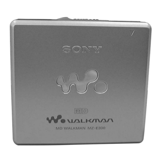
Sony MD WALKMAN MZ-E300 Servicehandleiding - Pagina 2
Blader online of download pdf Servicehandleiding voor {categorie_naam} Sony MD WALKMAN MZ-E300. Sony MD WALKMAN MZ-E300 34 pagina's. Portable minidisc player
Ook voor Sony MD WALKMAN MZ-E300: Gebruiksaanwijzing (2 pagina's), Specificaties (2 pagina's), Beperkte garantie (1 pagina's)

MZ-E300
TABLE OF CONTENTS
Specifications ........................................................................... 1
...................................................... 2
Preparing a Power Source .................................................. 3
To Connect the Headphones/Earphones ............................ 3
Playing an MD ................................................................... 3
3-2. Mechanism Deck ........................................................ 4
3-3. Main Board ................................................................. 5
3-4. Optical Pick-up ASSY ................................................ 5
.................................................................. 6
5-1. Explanation of IC Terminals ..................................... 13
5-2. Block Diagram .......................................................... 18
5-3. Printed Wiring Boards - Main Section (1/2) - ......... 19
5-4. Printed Wiring Boards - Main Section (2/2) - ......... 20
5-5. Schematic Diagram - Main Section (1/3) - ............. 21
5-6. Schematic Diagram - Main Section (2/3) - ............. 22
5-7. Schematic Diagram - Main Section (3/3) - ............. 23
6-1. Main Section ............................................................. 29
6-2. Mechanism Deck Section ......................................... 30
CAUTION
Use of controls or adjustments or performance of procedures
other than those specified herein may result in hazardous
radiation exposure.
Flexible Circuit Board Repairing
• Keep the temperature of the soldering iron around 270°C during
repairing.
• Do not touch the soldering iron on the same conductor of the
circuit board (within 3 times).
• Be careful not to apply force on the conductor when soldering or
unsoldering.
Notes on chip component replacement
• Never reuse a disconnected chip component.
• Notice that the minus side of a tantalum capacitor may be dam-
aged by heat.
SAFETY-RELATED COMPONENT WARNING!!
COMPONENTS IDENTIFIED BY MARK 0 OR DOTTED LINE
WITH MARK 0 ON THE SCHEMATIC DIAGRAMS AND IN THE
PARTS LIST ARE CRITICAL TO SAFE OPERATION.
REPLACE THESE COMPONENTS WITH SONY PARTS WHOSE
PART NUMBERS APPEAR AS SHOWN IN THIS MANUAL OR IN
SUPPLEMENTS PUBLISHED BY SONY.
ATTENTION AU COMPOSANT AYANT RAPPORT
À LA SÉCURITÉ!
LES COMPOSANTS IDENTIFIÉS PAR UNE MARQUE 0 SUR LES
DIAGRAMMES SCHÉMATIQUES ET LA LISTE DES PIÈCES
SONT CRITIQUES POUR LA SÉCURITÉ DE FONCTIONNEMENT.
NE REMPLACER CES COMPOSANTS QUE PAR DES PIÈCES
SONY DONT LES NUMÉROS SONT DONNÉS DANS CE MANUEL
OU DANS LES SUPPLÉMENTS PUBLIÉS PAR SONY.
2
................................... 31
SECTION 1
SERVICING NOTE
When repairing this device with the power on, if you remove the
main board, this device stops working.
In this case, you work without the device stopping by fastening
the hook of the Open/Close detection switch (S808).
Open/Close detection switch (S808)
Note on IC replacement
If using flux on replacing IC801 etc., clean it with alcohol or
equivalent, and after that, check carefully there are no dust or
rags in between pins.
Especially, be sure to check between pins 4 and 5.
