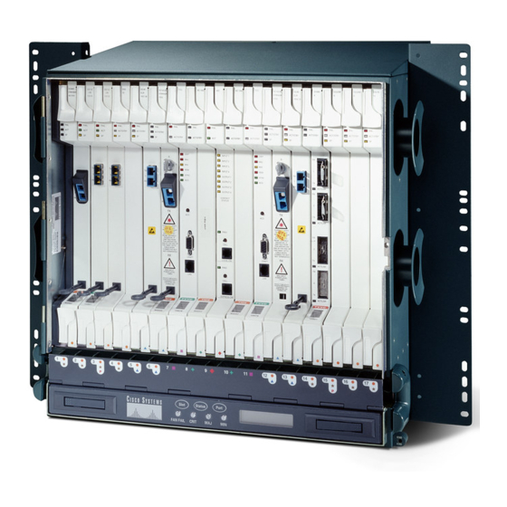
Cisco ONS 15454 Handleiding voor installatie-instructies - Pagina 9
Blader online of download pdf Handleiding voor installatie-instructies voor {categorie_naam} Cisco ONS 15454. Cisco ONS 15454 22 pagina's. Four-shelf and zero-shelf bay assembly
Ook voor Cisco ONS 15454: Installeer (32 pagina's), Installeer (32 pagina's), Uitpakken en installeren (42 pagina's), Uitpakken en installeren (40 pagina's)

Chapter 2 Install Cards and Fiber-Optic Cable
Table 2-4
XC Card Type
XCVT
XC10G/XC-VXC-10G
Refer to the card's reference section in the "Optical Cards" chapter of the Cisco ONS 15454 Reference
Manual for more information about slot and bandwidth restrictions.
Open the card latches/ejectors.
Step 2
Use the latches/ejectors to firmly slide the optical card along the guide rails until the card plugs into the
Step 3
receptacle at the back of the slot. If you install a card incorrectly, the FAIL LED flashes continuously.
Note
Step 4
Verify that the card is inserted correctly and close the latches/ejectors on the card. It is possible to close
the latches/ejectors when the card is not completely plugged into the backplane. Ensure that you cannot
insert the card any further.
Verify the LED activity:
Step 5
•
The red FAIL LED turns on for 20 to 30 seconds.
•
The red FAIL LED blinks for 35 to 45 seconds.
•
All LEDs blink once and turn off for 5 to 10 seconds.
•
The ACT or ACT/STBY LED becomes amber. The signal fail (SF) LED can persist until all card
ports connect to their far-end counterparts and a signal is present.
Step 6
If the card does not boot up properly, or the LED activity does not mimic
•
When a physical card type does not match the type of card provisioned for that slot in CTC, the card
might not boot. If an optical card does not boot, open CTC and ensure that the slot is not provisioned
for a different card type before assuming the card is faulty.
If the red FAIL LED does not turn on, check the power.
•
If you insert a card into a slot provisioned for a different card, all LEDs turn off.
•
•
If the red FAIL LED is on continuously or the LEDs behave erratically, the card is not installed
properly. Remove the card and repeat Steps
The MRC-12 card requires SFPs and the OC192SR1/STM64IO Short Reach and OC192/STM64 Any
Step 7
Reach (OC192-XFP) cards require XFPs to provide a fiber interface. If you installed any of these cards,
complete the
preprovision the SFPs or XFPs before installing them, complete the
XFP Device" task on page
When you are ready to install fiber, continue with the
Step 8
on page
78-17697-01
Maximum Bandwidth by Shelf Slot for the MRC-2.5G-4 in Different Cross-Connect
Configurations
If you install the wrong card in a slot, complete the
procedure on page
2-20.
"DLP-A469 Install a GBIC or SFP/XFP Device" task on page
21-42.
2-16.
NTP- A16 Install Optical Cards and Connectors
Maximum Bandwidth
in Slots 1 through 4
Maximum Bandwidth
and 14 through 17
in Slots 5, 6, 12, or 13
OC-12
OC-48
OC-48
OC-48
"NTP-A116 Remove and Replace a Card"
2
to 5.
"DLP-A461 Preprovision an SFP or
"NTP-A247 Install Fiber-Optic Cables" procedure
Cisco ONS 15454 Procedure Guide, R8.0
Step
5, check the following:
21-57. If you want to
2-9
