Cisco ONS 15454 Uitpakken en installeren - Pagina 26
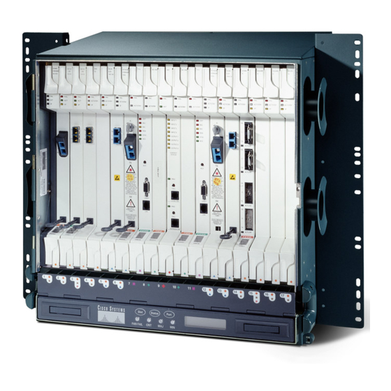
Blader online of download pdf Uitpakken en installeren voor {categorie_naam} Cisco ONS 15454. Cisco ONS 15454 40 pagina's. Four-shelf and zero-shelf bay assembly
Ook voor Cisco ONS 15454: Handleiding voor installatie-instructies (22 pagina's), Installeer (32 pagina's), Installeer (32 pagina's), Uitpakken en installeren (42 pagina's)
Fuse and Alarm Panel Wiring
The AIC-I requires a shelf assembly running Software Release 3.4.0 or later. The AIC-I uses wire-wrap
Note
field pin assignments according to the layout in
Perform wire-wrapping according to the T (Tip) and R (Ring) diagram in
Figure 25
(TIP) T = WHT/BLU
(RING) R = BLU/WHT
FAP Output and Input Power
Route output and input power according to local site practice. Refer to the latest release of the
Cisco ONS 15454-FAP-LVD Operations Guide for more information.
output and input lugs and wiring and
Unpacking and Installing the Cisco ONS 15454 Four-Shelf and Zero-Shelf Bay Assembly
26
Wire-Wrap Pin Layout in a Release 3.4 and Later ANSI Shelf Assembly
T R
1
1
1
2
2
2
3
3
3
4
4
4
BITS
LAN
FG1
FG2
FG3
A1 - WHT/BLU
B1 - WHT/ORN
A2 - WHT/GRN
B2 - WHT/BRN
Figure
25.
T R
1
7
ACO
2
8
3
5
9
4
6
10
ENVIRONMENTAL ALARMS
IN
IN/OUT
IN
IN
FG4
FG5
FG6
WHT/SLT - Fuse A
RED/BLU - Fuse B
Table 2 on page 28
Figure
25.
1
1
1
1
2
2
2
2
3
3
3
3
4
4
4
4
MODEM
CRAFT
LOCAL ALARMS
VIS
FG7
FG8
FG9
FG10
Figure 26
through
lists lug wiring positions.
11
12
IN
AUD
FG11
FG12
Figure 30
show
78-15720-04